Showing posts with label Profile View. Show all posts

Tuesday, September 13, 2011

Multiple Surface Dilemma (Part 3)

NOTE: This is Part 3 of the Multiple Surfaces Dilemma Series. You can view Part 1 of the series here. In Part 1 of this series, a surface named ComboSurface was created. Make sure you create that surface in your drawing before proceeding with these steps.

Wouldn't it be nice to have a visual representation of the target minimum depth in the profile view while you're designing your pipe network? Here's a way to make that happen:

Create a new surface in your current drawing and name it "MinimumDepth". You can use the same procedure as described for creating the "ComboSurface" in the original post of this series. Just as with the ComboSurface, this surface will not need to be displayed so set the surface style to "_No Display" as it's created.

To add some substance to the new surface, you'll need to paste the ComboSurface into the MinimumDepth surface. Again, use the same procedure described in the original post of this series except you'll be pasting a different surface.

Under the MinimumDepth surface definition, locate the Edits option, right click, and select "Raise/Lower Surface".
 

When prompted at the command line, enter -4 to lower the MinimumDepth surface 4 feet.

The last thing to do is create a profile based on the MinimumDepth surface:
  1. On the home ribbon tab, locate the "Create Design" Panel, left click on Profiles, then choose "Create Surface Profile" from the drop down list.


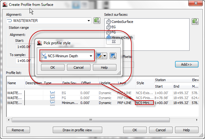
  2. In the Create Profile from Surface dialog box, select the alignment, select the MinimumDepth surface, then left click on Add.


  3. Change the style of the newly created profile to a style called "Minimum Depth". This style places the profile linework on a layer that doesn't plot and has a forced color and linestyle to look different from all other profiles.


The final product looks like this:


Monday, September 12, 2011

Multiple Surface Dilemma (Part 2)

NOTE: This is Part 2 of the Multiple Surfaces Dilemma Series. You can view Part 1 of the series here. In Part 1 of this series, a surface named ComboSurface was created. Make sure you create that surface in your drawing before proceeding with these steps.

In this post, I'm going to assign the ComboSurface to the Pipe Network in the network properties dialog box.
  1. Since the pipe network has already been created in my drawing, I just need to locate it in the Prospector tab of Toolspace, select it, right click, and choose Network Properties.


  2. Set the surface name to ComboSurface.


Now as I place pipes and structures in this pipe network, the correct elevation will be used/reported (EG or FG) according to the location of the pipe or structure. Remember, you don't want this surface visible, just create it and select it from the list of surfaces when needed.

Friday, May 6, 2011

Don't Forget These Commands...Part 1

There are so many commands in AutoCAD and Civil 3D that we use every day. Some of them are available via toolbars, menus, or the ribbon, that you only have to learn where to find them, not memorize them.

In my case, there are a few commands or system variables that just get lost in the deep void of space inside my brain. Here's a few of them:

LINEWORKSHRINKWRAP - Creates a boundary around a selection set of objects.

PELLIPSE - Setting this variable to 1 will draw an ellipse as a polyline.

FILEDIA - This variable gets set to 0 during some commands and/or lisp routines. If AutoCAD crashes, you may have to reset it to 1 to display dialog boxes instead of command line prompts.

'STAE - Transparent command for Civil 3D to select station from the parent alignment of a profile view.

'SSE - Transparent command for Civil 3D to select station from the parent alignment of a profile view and elevation from a surface.

'PSE - Transparent command for Civil 3D to select station and elevation from a profile view.

'ZTP - Transparent command for Civil 3D to zoom to a point or range of points.

There's plenty more to add to this list, but it's a start.

Thursday, May 5, 2011

Water Structures in Profile View

You know that special symbol for water valves and fire hydrants that the engineers want to see in profile views of water lines? Ours looks something like this:


If you think it's a structure style, then you're wrong. It's actually a label style that uses several custom expressions. I use a block that is a rectangle on a no plot layer for the structure in profile view. You can leave the no plot structure visible, or you can turn off the display of the structure in profile view once you've added your labels.

This label will move with the structure, adjust to the size of the structure, and adjust to changes in the surface referenced in the structure. Adjusting the custom expressions, you can control how far all four sides of the rectangle are from the center of the structure based on the size of the structure.

Now if only we could assign a default label style to each structure in profile view I could finish my P&P sheets even quicker. For now, I'm just happy that I don't have to place a dynamic block at each structure then remember to go back and move it as my structure moves to an updated location.

Thursday, April 10, 2008

PVLS PART 4: Offsetting a Profile View Label

This is Part 4 of a series on Profile View Label Styles (PVLS). This post may not make a whole lot of sense if you haven't seen the previous posts in this series. Please take a moment to read them before continuing to read this one. Here's a link to each:

PVLS PART 1: Creating Profiles for Labeling Crossing or Connecting Pipe Flowline Elevations

PVLS PART 2: Creating the Style for the Connecting Pipe Flowline Elevation Label

PVLS PART 3: Labeling the Crossing or Connecting Pipe Flowline Elevations

To use the Offset Style created in this series, you'll need to create the label style first. (Instructions for creating an offset label style can be found Part 2 of this series.

After the style has been created, right click on the style and select New... in the Settings tab of the Toolspace. For Profile Views, this will create a "Child" of the original style. It will have all the same properties and components of the original style at the time that it is created except those that you change.

On the Information tab, rename the text inside the brackets [child] to [RT-0.3]. That means that we will be creating a style that moves the text right 0.3 inches. Go ahead and left click on Apply then select the Layout tab.

Remember how we deleted the original text so that the first component was "Line for Text". This is where it comes into play.

Go to the Line section and change the Start Point X Offset to 0.3, then Apply and OK. Now place the style in the drawing or change one of the existing labels to use this style instead. Here's a screen capture of the original parent style and the new offset RT child style.


There are other ways to change the style as well. Try changing these values and see how they affect the style:
  • The length of the "Line at Insertion Point"
  • The length of the "Line for Text"
  • The Start Point Y Offset of the "Line for Text"
You should never change the values of the "Offset Connection Line", because they will always follow the start/end of the other lines in the style.

Well, that's it for my series on Profile View Label Styles. I hope you found it useful. Feel free to post a comment if you have questions or if you just want to request a topic for a future post.

Technorati Tags:

PVLS PART 3: Labeling the Crossing or Connecting Pipe Flowline Elevations

This is Part 3 of a series on Profile View Label Styles (PVLS). You should also read Part 1 and Part 2 of this series for additional information.

To label a crossing and/or connecting pipe flowline elevation, you'll need the style created in Part 2 of this series and profiles for both the main line and the crossing/connecting pipes as described in Part 1 of this series.

After you have the style and profiles created in your drawing, the rest is really simple.
  1. Zoom into the connecting pipe that you want to label.
  2. From the Civil 3d Profile menu, select "Add Profile View Labels", then "Add Profile View Labels...".
  3. In the Add Labels dialog box, select the style that you created from Part 2 of this series (mine was called Connecting Pipe Label).
  4. Choose a Marker style if you want one. I don't generally use one for this style.
  5. Left click on the Add command button.
  6. You will be prompted to select a profile view. Select the profile view by left clicking on one of the grid lines, not the actual profile.
  7. When asked to specify a station, select the endpoint at the flowline of the crossing pipe shown in the profile view.
  8. When asked to specify an elevation, you can either select the same point or specify an elevation for the insertion point of the label.
  9. Repeat this process for other connecting pipe labels that are visible in this profile view.
  10. If you need to add labels in other profile views, you'll need to left click on the Add command button again to select a different profile view.
So now the label is placed, but there aren't any elevations shown. Here's the secret:
  1. Select all the connecting pipe labels in one profile view and then look at the properties listed on the labels. There is a Civil 3D section that contains a listing for Profile1 Object and Profile2 Object. They will be set to by default.
  2. Left click on the for Profile1 Object and set that to the profile you created for the flowline of the main pipe.
  3. Left click on the for Profile2 Object and set that to the profile you created for the crossing and/or connecting pipes and pipe size changes.
Now you have the flowline elevations and all you have to do is editlabeltext on the style to change the name of the utility line and modify the pipe sizes. As I said in my first post, I'm sure you can take this style further to get the pipe sizes in it. Also, you would need to make a copy of the style and modify the text for grade breaks, and crossing pipes.

Well, that's it for Part 3. In Part 4, I will describe how to use the offset capability that we put in place when we created the Profile View Station Elevation Label Style in Part 2 of this series.

Technorati Tags:

PVLS PART 2: Creating the Style for the Connecting Pipe Flowline Elevation Label

This is Part 2 of a series on Profile View Label Styles (PVLS). You can view Part 1 of the series here.

Here's the step by step guide to creating the Station Elevation Profile View Label Style. The way this style is created will enable you to easily establish offsets in child styles as needed. That will be explained in a Part 4 of this series.
  1. If toolspace is not visible, type showts at the command line and press enter.
  2. Select the Settings tab.
  3. Double click "Profile View" in the list under your current drawing name.
  4. Double click "Label Styles".
  5. Right click "Station Elevation" and select "New...".
  6. On the Information tab, type a name for your style. I'll use Connecting Pipe Label for this example.
  7. On the General tab, set the layer as required. I'll use PROF-VIEW-TX for this example.
  8. On the Layout tab, delete the default "Station & ELevation" component (yes, the "L" is really capitalized) that is created by clicking on the near the top middle of the Label Style Composer dialog box. I do this because I want a different component to be the first one that appears when the Layout tab is selected in the future.
  9. Select Line from the Create Component dropdown list.
  10. Under the General section:
    1. Change the Name property to Line for Text,
    2. Set the Start point anchor point to Middle Center.
  11. Under the Line section:
    1. Change the Length to 2.0000",
    2. Set the Angle to 270° 00' 00",
    3. Set the Start Point Y Offset to -0.5000". This moves the beginning of the line down 0.5 inches from the point you select for placing the label.
  12. At this point, you're probably looking at the preview side of the Label Style Composer dialog box to see how things are looking. Unfortunately, the default preview state for a Profile View Station Elevation Label is set to Depth Label Style. So click the drop down arrow near the upper right corner of the Label Style Composer dialog box and select "Station Elevation Label Style" to watch the style update as you apply the changes.
  13. At this point, go ahead and select Apply so that everything up to this point will be saved.
  14. Create another line component (same as step 9).
  15. Under the General section:
    1. Change the Name property to Line at Insertion Point,
    2. Set the Start point anchor point to Middle Center.
  16. Under the Line section:
    1. Change the Length to 0.2500",
    2. Set the Angle to 270° 00' 00".
  17. Now create one more line component (same as step 9). This may seem unusual, but it will make sense at the end of the post.
  18. Under the General section:
    1. Change the Name property to Offset Connection Line,
    2. Set the Start point anchor component to Line at Insertion Point,
    3. Set the Start point anchor point to End,
    4. Set the Use End Point Anchor to True,
    5. Set the End Point Anchor Component to Line for Text,
    6. Verify that the End Point Anchor Point is set to Start.
  19. Select Apply again to save the changes up to this point. The preview tab will show that the label currently appears as if there is just one solid line.
  20. Create a text component from the create component list.
  21. Under the General section:
    1. Change the Name property to Station and Flowline Text,
    2. Set the Start point anchor point to Line for Text,
    3. Set the Anchor Point to End.
  22. Under the Text section:
    1. Edit the Contents as follows:
      1. On the format tab, set the Justification to Left,
      2. Insert text appropriate for the style you are creating. For my example, I used this text:
        STA <[Station Value(Uft|FS|P2|RN|AP|Sn|TP|B2|EN|W0|OF)]> SSL-XX=
        STA 1+00 SSL-XX
        FL (XX")=<[Profile1 Elevation(Uft|P2|RN|AP|Sn|OF)]>
        FL (XX")=<[Profile2 Elevation(Uft|P2|RN|AP|Sn|OF)]>
        I also force the XX values to a different color so that I know that these values have to be manually edited and updated as required. It ends up looking something like this:
    2. Set the Attachment point to Bottom Right (Don't ask me why. I think it should be set to Top Left, but once the text is perpendicular to the view, it seems that you have to set it to the opposite of what you think it should be.)
  23. Apply, OK, and your style is complete.
Well, that's it for Part 2. In Part 3, I will describe how to place the Profile View Station Elevation Label Style that you just created.

Technorati Tags:

PVLS PART 1: Creating Profiles for Labeling Crossing or Connecting Pipe Flowline Elevations

This is Part 1 of a series on Profile View Label Styles (PVLS). I will discuss how to label the flowlines of connecting pipes in a profile view. Armed with this information, you should be able to create your own style that shows flowlines of pipes at crossings and at changes in pipe sizes.

Well this is one label style with which I've been wrestling for some time. Then while creating an offset label style the other day, it just hit me how easy it would be to get the two flowline elevations into one style. Now, at this point, the pipe size in this particular style has to be edited manually, but maybe this style might give you some ideas on how to get everything you want labeled automatically.

The first thing you need to do is create a profile style with Line, Circular Curve, Symmetrical Parabola, and Asymmetrical Parabola component types visible, but on a "no-plot" layer. For my style, I've create a layer called _no-plot-profile and set the Plot property to "No".


Now create a profile by layout that follows the flowline of the main pipe in your profile view. Be sure to use the "no-plot-profile" style that you just created. This profile can also be used to label your pipe flowline elevations (such as the elevations shown in a band style).


Now create a second profile by layout that connects the flowline of all your crossing or connecting pipes. You can also tag the end of the smaller pipe at a pipe change (since a profile can't be exactly vertical). The second profile should look something like this:


Here's a zoomed in view of the three major locations where I use the "crossing pipe" profile. (Just click on the image to see an enlarged view.)


Well, that's it for Part 1. In Part 2, I will describe how to create the Profile View Station Elevation Label Style.

Technorati Tags:

Thursday, February 28, 2008

What? You Don't Use Bands?

That was the reaction I received during a presentation at my local user group meeting last week.  That group may not remember anything else I said, but that comment definitely got a reaction from the crowd.   So here's the story behind that statement...

Some engineers and companies are very particular about how certain items are labeled on their profile views.  I was working with one of those engineers on a project last year when I ran into a snag.  I was supposed to show the elevations of the profile in the "band" at the bottom of the profile view but I had to add the text "TC=" in front of the elevation.   The problem was that the "TC=" text appeared even on stations that had no profile. 

 Band_Style

Obviously, that wasn't going to work, so I had to find a different way to display this label.  Having recently made some changes to the default profile styles in the company template, I decided to give something a try.  I created a profile label style that looked just like the band style, but it only appears where the profile exists.  That means if the profile only exists from station 1+00 to 12+50, then you'll only get labels from station 1+00 to 12+50 according to the major and minor station labels requested. 

Band_Style2

So here's how you create and use this style:

  1. Open or create a drawing in Civil 3D.
  2. Make sure the toolspace is visible (command:  showts)
  3. Select the Settings tab of the Toolspace.
  4. Double click "Profile" from the list of objects.
  5. Double click "Label Styles".
  6. Double click "Station".
  7. Double click "Major Station"
  8. Now you should see a list of the existing Profile Major Station Labels in this drawing.  The list may only contain "Standard".
  9. Right click on "Major Station" and choose "New..."
  10. Select the Information tab and change the Name of the Label Style to "XX-FG-LT". Replace the XX with the initials of your company.
  11. Apply.
  12. Select the General Tab.
    • Change the Layer to the one of your choice.
    • Set the Orientation Reference to either View or World Coordinate System.  Band_Style3 
  13. Select the Layout tab.
    • Left click the Band_Style4 enough times to remove all existing components from the list.
    • Left click the Band_Style5 to insert a new "default" text object.
    • Change the Name value from "Text.1" to "Profile Elevation".
    • Set the Anchor Point to "Anchor Station Extension"
    • Modify the Contents Value:
      • Left click on the "Label Text" box then left click on the Band_Style6 to change the text value for this label
      • Select all the text in the Text box on the right of the Text component Editor - Contents dialog box and replace it with the desired "prefix text" in the same location (TC=)
      • Make sure your cursor is after the last character of the "prefix text"
      • From the Properties drop down list, select Profile Elevation
      • Set the Precision, Rounding, Decimal character, Sign and Output as desired for your project
      • Left click the CreateMacro to create the macro
      • The result should look something like this:  Band_Style6
      • OK
    • Set the Text Height to the desired value
    • Change the Rotation Angle to 90
    • Change the Attachment to Top Left
    • Change another other border and dragged state settings as required.
  14. Apply
  15. OK

Now all that's left to do is add your new style to a Label Set.  The tricky part is that you have to set the Dim anchor opt to "Profile View Bottom" and adjust your Dim anchor val to an appropriate setting.

Band_Style7

So, that's all it takes to create a band style that only places labels where the profile exists.

Technorati Tags: , , ,