There is an updated version of the Autodesk Screencast. It was posted on March 29, 2016. You can download either the Windows or Mac version here.
If you have not yet tried the Autodesk Screencast recording software, you should download your free copy today. Autodesk Screencast records basic audio and video in almost any application as well as keystrokes and mouse clicks used during recordings in Autodesk products such as AutoCAD.
The Autodesk Screencast software also allows you to make some edits to the timeline such as removing a selected portion of the recording.
Once you've recorded and made adjustments to the timeline, you can post the recording on the Autodesk Knowledge Network.
The recordings you upload can be marked as private, public, or unlisted.
Read more about Autodesk Screencast here then search for other useful tips posted there as well. You can even subscribe to a user's Screencast account to get notified each time a new video or AKN is posted by that user.
A blog about AutoCAD and AutoCAD Civil 3D for civil engineering professionals.
Showing posts with label AutoCAD. Show all posts
Tuesday, March 29, 2016
What's your favorite new feature in AutoCAD 2017?
In case you haven't heard, AutoCAD 2017 is now available for download. Many websites are now posting the new features you'll find in this version. There's even a feature list comparing the last few versions of AutoCAD for you to review.
In case you want to learn about the new features in AutoCAD 2017, begin with the (1) Learn portion of the Start Tab. There's a (2) What's New video showing the latest and greatest new features in AutoCAD 2017. The (3) Getting Started Videos can help show you around the interface and help you start using the software. The (4) Learning Tips are useful for many disciplines and the right and left arrow buttons can be used to access additional tips. Finally there's an (5) Online Resources section with links to additional learning resources, such as The Hitchhiker's Guide to AutoCAD Basics.
You can also access Learning Videos in the
Autodesk Desktop App.
If you initially decided not to migrate/import your settings from your previous version of AutoCAD, you can later access this newly updated feature using the Migrate From a Previous Release command in the Start Menu. You will need to close AutoCAD 2017 to run this command.
The new Migrate Custom Settings dialog is more user friendly than previous versions.
Centerlines and centermarks are new features for AutoCAD 2017 as well. They are dynamic, which means they move with the source objects as shown in this video.
There are more new features such as improved PDF import support and graphics enhancements including making arcs look like arcs instead of segmented arcs even during a move command. For now, though, I want to discuss one of my favorite improvements in AutoCAD 2017. You might not even notice it until I describe it to you.
In previous versions of AutoCAD, when you click the New Folder icon, you had to then select the folder and right click or select the folder twice, slowly, to edit the folder name.
In AutoCAD 2017, the folder name is highlighted by default upon creation. That means you can start typing a folder name immediately after clicking the New Folder icon.
Yes this is how it works in Windows Explorer, but now it works the same way in AutoCAD 2017.
That leads me to my initial question: What's your favorite new feature in AutoCAD 2017?
In case you want to learn about the new features in AutoCAD 2017, begin with the (1) Learn portion of the Start Tab. There's a (2) What's New video showing the latest and greatest new features in AutoCAD 2017. The (3) Getting Started Videos can help show you around the interface and help you start using the software. The (4) Learning Tips are useful for many disciplines and the right and left arrow buttons can be used to access additional tips. Finally there's an (5) Online Resources section with links to additional learning resources, such as The Hitchhiker's Guide to AutoCAD Basics.
You can also access Learning Videos in the
Autodesk Desktop App.If you initially decided not to migrate/import your settings from your previous version of AutoCAD, you can later access this newly updated feature using the Migrate From a Previous Release command in the Start Menu. You will need to close AutoCAD 2017 to run this command.
The new Migrate Custom Settings dialog is more user friendly than previous versions.
Centerlines and centermarks are new features for AutoCAD 2017 as well. They are dynamic, which means they move with the source objects as shown in this video.
There are more new features such as improved PDF import support and graphics enhancements including making arcs look like arcs instead of segmented arcs even during a move command. For now, though, I want to discuss one of my favorite improvements in AutoCAD 2017. You might not even notice it until I describe it to you.
In previous versions of AutoCAD, when you click the New Folder icon, you had to then select the folder and right click or select the folder twice, slowly, to edit the folder name.
In AutoCAD 2017, the folder name is highlighted by default upon creation. That means you can start typing a folder name immediately after clicking the New Folder icon.
Yes this is how it works in Windows Explorer, but now it works the same way in AutoCAD 2017.
That leads me to my initial question: What's your favorite new feature in AutoCAD 2017?
Monday, December 8, 2014
Resize Me!
Sometimes you learn things that you don't realize others haven't seen yet. During the CV6726-P - Attack of the Roundabouts: Conquer Them with Vehicle Tracking class taught by Brian Levendowski, Infrastructure Industry Manager, CAD Technology Center, Inc., I found this to be the case with resizing of viewports in the Model tab. When Brian did this during his presentation, the previously silent classroom was filled with Oohs and Aahs and the sound of pencils/pens and paper immediately followed. Since so many in that class had not seen this feature I decided to share it with you.
Here is the step by step description.
You can also add viewports by using the + as the beginning point of the left click, hold, and drag location. By dragging an existing viewport near another viewport boundary you can delete an existing viewport. To see this in greater detail, I refer you to Greg Battin's AutoCAD Tips blog post titled AutoCAD 2015 Resize Model Space Viewports.
Here is the step by step description.
- Open any drawing with version AutoCAD 2015 or later, then set the View ribbon tab current. This also works in verticals such as Civil 3D.

Select the View Ribbon Tab - Locate the Model Viewports panel and left click on the words Viewport Configuration to activate the drop down selection list.

Accessing the Viewport Configuration drop down selection list. - From the drop down selection list, left click on Two: Vertical (or any other option except Single) to view multiple viewports on the Model tab of your current drawing.

Select a viewport configuration with multiple viewports. - With the multiple viewports visible, you can now hover your cursor over any of the adjoining lines between viewports, left click, hold, and drag to the desired location. When you get the line moved to the desired location, release the left mouse button.
You can also add viewports by using the + as the beginning point of the left click, hold, and drag location. By dragging an existing viewport near another viewport boundary you can delete an existing viewport. To see this in greater detail, I refer you to Greg Battin's AutoCAD Tips blog post titled AutoCAD 2015 Resize Model Space Viewports.
Wednesday, February 13, 2013
How Do I "EXPLODE" a Group?
I was asked this question twice this week already so I thought it would be good to post the answer for others.
To "explode" a group, use the AutoCAD command: UNGROUP
Of course "exploding" a group may not be the best choice for every situation. In groups, if you just want to grip edit something within the group, set the system variable GROUPDISPLAYMODE to 0. This setting will display grips on all objects in the selected group. It will preserve the group while allowing you access to grips to make changes to individual objects within the group.
Here are a few images to show the difference between the three settings available in the GROUPDISPLAYMODE system variable. Each image shows a group consisting of an mtext object and a rectangular wipeout that has been selected within a drawing.
With GROUPDISPLAYMODE set to 0, the grips on all objects in the selected group will be displayed. Notice that I can adjust the limits of the wipeout or the width of the mtext object.
With GROUPDISPLAYMODE set to 1, a single grip at the center of the grouped object will be displayed. Notice the single grip at the center? With this setting I can't adjust the limits of the wipeout or the width of the mtext object.
With GROUPDISPLAYMODE set to 2, a group bounding box and a single grip at the center of the grouped object will be displayed. The only difference between this setting and the previous setting is that with the bounding box visible I can see the limits of the objects in the group.
To "explode" a group, use the AutoCAD command: UNGROUP
Of course "exploding" a group may not be the best choice for every situation. In groups, if you just want to grip edit something within the group, set the system variable GROUPDISPLAYMODE to 0. This setting will display grips on all objects in the selected group. It will preserve the group while allowing you access to grips to make changes to individual objects within the group.
Here are a few images to show the difference between the three settings available in the GROUPDISPLAYMODE system variable. Each image shows a group consisting of an mtext object and a rectangular wipeout that has been selected within a drawing.
![]() | |
| GROUPDISPLAYMODE set to 0 |
![]() |
| GROUPDISPLAYMODE set to 1 |
![]() |
| GROUPDISPLAYMODE set to 2 |
Friday, January 18, 2013
Autodesk University 2012 Classes Posted
The materials and recordings for the 2012 Autodesk University classes have been posted. You can access the class list here:
You must have an AU account to access the classes. If you don't have an AU account, you can sign up for one here.
Since the announcement about this just went public, you may notice the website being a bit slow to respond. Just be patient because there are so many good classes available. In case you feel overwhelmed when you see the class listing, just refine your search such as Software: Civil 3D. There's even a filter for Language: Portuguese.
Enjoy!
You must have an AU account to access the classes. If you don't have an AU account, you can sign up for one here.
Since the announcement about this just went public, you may notice the website being a bit slow to respond. Just be patient because there are so many good classes available. In case you feel overwhelmed when you see the class listing, just refine your search such as Software: Civil 3D. There's even a filter for Language: Portuguese.
Enjoy!
OSNAPZ to the Rescue
Do you remember the Almond Joy/Mounds commercials?
The OSNAPZ command in AutoCAD reminds me of those commercials.
The OSNAPZ command is an easy way to switch between snapping to an elevation and forcing an elevation when creating or editing AutoCAD objects. When drafting in both the Civil Engineering and Land Surveying fields, both options are useful.
From the AutoCAD help documentation:
With OSNAPZ set to 0, OSNAP uses the Z-value of the specified point. For a polyline, the elevation selected for the first vertex will be assigned as the elevation of the polyline.
With OSNAPZ set to 1, OSNAP substitutes the Z-value of the specified point with the elevation (ELEV) set for the current UCS. With the system variable ELEV set to 0, the elevation will default to 0 for all selected points.
Now hopefully I can finally get that song out of my head.
(Sometimes you feel like a nut, sometimes you don't.)
The OSNAPZ command in AutoCAD reminds me of those commercials.
(Sometimes I want elevation, sometimes I don't.)
The OSNAPZ command is an easy way to switch between snapping to an elevation and forcing an elevation when creating or editing AutoCAD objects. When drafting in both the Civil Engineering and Land Surveying fields, both options are useful.
From the AutoCAD help documentation:
With OSNAPZ set to 0, OSNAP uses the Z-value of the specified point. For a polyline, the elevation selected for the first vertex will be assigned as the elevation of the polyline.
With OSNAPZ set to 1, OSNAP substitutes the Z-value of the specified point with the elevation (ELEV) set for the current UCS. With the system variable ELEV set to 0, the elevation will default to 0 for all selected points.
Now hopefully I can finally get that song out of my head.
Tuesday, December 11, 2012
Slow Down and Render This
Yesterday, I received an email with an attached drawing. Verbally, the request was to determine why the drawing is so slow, especially when using the zoom extents.The email included the following additional information:
This file was messing up badly on Wednesday...crazy slow, etc.
This morning with my new reload of AutoCAD 2011, it wasn't as bad... but still has signs of corruption...
One thing that I noticed is that the TIN in the V-TINN-VIEW layer doesn't look right... the contours are fine... but I didn't know if you had a fix for that...
There are lots of things that can cause a drawing to be a little slow. I have a list of things I check in a drawing but I knew that many of those had already been checked by the owner of this drawing. The comment about the TIN not looking correct was definitely a clue to the problem as was the knowledge that the user had recently been working with point clouds including some third party software.
I knew the fresh install and absence of the third party software had ruled out that being the issue so my first option was simply to open the drawing. Here's what I saw in the bottom left corner of the application:
This is not the ucs icon that I typically see in my drawings. The thickness of the ucs icon elements was an indication to me that the visual style was set to something other than 2D Wireframe.
To verify my suspicion, on the View ribbon tab, I selected the dropdown on the Views Panel and found the visual style was set to Hidden.
I left clicked on the Hidden visual style and changed the visual style to 2D Wireframe.
Now the ucs icon looks as expected and the speed of the drawing has returned to "normal".
Now if you are using AutoCAD 2012 or later, take a look at the upper left corner of model space. There you should find the Visual Style Controls.
As you can see, the visual style in this drawing is now set to 2D Wireframe. Changing this setting from Hidden to 2D Wireframe greatly improved the speed of the drawing.
This file was messing up badly on Wednesday...crazy slow, etc.
This morning with my new reload of AutoCAD 2011, it wasn't as bad... but still has signs of corruption...
One thing that I noticed is that the TIN in the V-TINN-VIEW layer doesn't look right... the contours are fine... but I didn't know if you had a fix for that...
There are lots of things that can cause a drawing to be a little slow. I have a list of things I check in a drawing but I knew that many of those had already been checked by the owner of this drawing. The comment about the TIN not looking correct was definitely a clue to the problem as was the knowledge that the user had recently been working with point clouds including some third party software.
I knew the fresh install and absence of the third party software had ruled out that being the issue so my first option was simply to open the drawing. Here's what I saw in the bottom left corner of the application:
This is not the ucs icon that I typically see in my drawings. The thickness of the ucs icon elements was an indication to me that the visual style was set to something other than 2D Wireframe.
To verify my suspicion, on the View ribbon tab, I selected the dropdown on the Views Panel and found the visual style was set to Hidden.
I left clicked on the Hidden visual style and changed the visual style to 2D Wireframe.
Now the ucs icon looks as expected and the speed of the drawing has returned to "normal".
Now if you are using AutoCAD 2012 or later, take a look at the upper left corner of model space. There you should find the Visual Style Controls.
As you can see, the visual style in this drawing is now set to 2D Wireframe. Changing this setting from Hidden to 2D Wireframe greatly improved the speed of the drawing.
Wednesday, December 14, 2011
Don't Forget These Commands...Part 4
Here's another system variable that I forget because I only seem to need it when working on drawings from others:
XCLIPFRAME
Here's the definition from the AutoCAD Help Menu:
When this system variable is set to 0 and you xclip an xreference drawing, you can't see the boundary of the xclip and therefor you can't invert the selection. We set this variable to 2 in our templates so that we can see the frame (for adjusting and inverting as needed), but the frame won't plot.
XCLIPFRAME
Here's the definition from the AutoCAD Help Menu:
When this system variable is set to 0 and you xclip an xreference drawing, you can't see the boundary of the xclip and therefor you can't invert the selection. We set this variable to 2 in our templates so that we can see the frame (for adjusting and inverting as needed), but the frame won't plot.
Wednesday, September 21, 2011
Monday, September 12, 2011
Don't Forget These Commands...Part 3
So I know that I typically blog about Civil 3D, but after assisting with an issue in Microstation this morning, I realized that I should add this keyin command to my "Don't Forget" list.
The issue was that a linestyle looked fine in one drawing, but different when referenced into another drawing. I found some good information on the Bentley site with a quick Google search. Here's a direct link to that page:
http://communities.bentley.com/products/microstation/w/microstation__wiki/setting-linestyle-scale-in-microstation-v8-cs.aspx
We used the keyin command window to set active linestylescale to 20 in both drawings and that fixed the display problem we were having.
So as not to disappoint the Civil 3D readers of this blog, I'll add these commands to the "Don't Forget" list as well. The descriptions are taken from the System Variables.:
LTSCALE - Sets the global linetype scale factor.
MSLTSCALE - Scales linetypes displayed on the model tab by the annotation scale.
PSLTSCALE - Controls the linetype scaling of objects displayed in paper space viewports.
I typically keep all three of these system variables set to 1.
The issue was that a linestyle looked fine in one drawing, but different when referenced into another drawing. I found some good information on the Bentley site with a quick Google search. Here's a direct link to that page:
http://communities.bentley.com/products/microstation/w/microstation__wiki/setting-linestyle-scale-in-microstation-v8-cs.aspx
We used the keyin command window to set active linestylescale to 20 in both drawings and that fixed the display problem we were having.
So as not to disappoint the Civil 3D readers of this blog, I'll add these commands to the "Don't Forget" list as well. The descriptions are taken from the System Variables.:
LTSCALE - Sets the global linetype scale factor.
MSLTSCALE - Scales linetypes displayed on the model tab by the annotation scale.
PSLTSCALE - Controls the linetype scaling of objects displayed in paper space viewports.
I typically keep all three of these system variables set to 1.
Thursday, August 4, 2011
Add Spice To Your Right Click Menu Options
Well, technically I'm going to show you how to add Isolate/Unisolate Layers to your right click menu, but spice sounded better for the title...
- Execute the CUI command.
- Scroll down to the Shortcut Menus option and left click on the +.
- Look through the expanded list and left click on the + by Context menu for edit mode.
- Right click on Context menu for edit mode and select New Sub-menu.
- Rename the menu item Menu1 to Isolate Layers.
- Drag the Isolate Layers sub-menu to the location just above the Isolate Objects sub-menu.
- In the Search box under the Command List section, enter layer iso.
- Drag the Layer Isolate command onto the Isolate Layers sub-menu that you previously created.
- Repeat steps 7 & 8 for Layer Unisolate.
- You can change the order of the commands under the sub-menu if necessary.
- You can change the display name of the command in the sub-menu if necessary.
- OK to get out of the CUI editor and you're done.
Friday, May 6, 2011
Don't Forget These Commands...Part 1
There are so many commands in AutoCAD and Civil 3D that we use every day. Some of them are available via toolbars, menus, or the ribbon, that you only have to learn where to find them, not memorize them.
In my case, there are a few commands or system variables that just get lost in the deep void of space inside my brain. Here's a few of them:
LINEWORKSHRINKWRAP - Creates a boundary around a selection set of objects.
PELLIPSE - Setting this variable to 1 will draw an ellipse as a polyline.
FILEDIA - This variable gets set to 0 during some commands and/or lisp routines. If AutoCAD crashes, you may have to reset it to 1 to display dialog boxes instead of command line prompts.
'STAE - Transparent command for Civil 3D to select station from the parent alignment of a profile view.
'SSE - Transparent command for Civil 3D to select station from the parent alignment of a profile view and elevation from a surface.
'PSE - Transparent command for Civil 3D to select station and elevation from a profile view.
'ZTP - Transparent command for Civil 3D to zoom to a point or range of points.
There's plenty more to add to this list, but it's a start.
In my case, there are a few commands or system variables that just get lost in the deep void of space inside my brain. Here's a few of them:
LINEWORKSHRINKWRAP - Creates a boundary around a selection set of objects.
PELLIPSE - Setting this variable to 1 will draw an ellipse as a polyline.
FILEDIA - This variable gets set to 0 during some commands and/or lisp routines. If AutoCAD crashes, you may have to reset it to 1 to display dialog boxes instead of command line prompts.
'STAE - Transparent command for Civil 3D to select station from the parent alignment of a profile view.
'SSE - Transparent command for Civil 3D to select station from the parent alignment of a profile view and elevation from a surface.
'PSE - Transparent command for Civil 3D to select station and elevation from a profile view.
'ZTP - Transparent command for Civil 3D to zoom to a point or range of points.
There's plenty more to add to this list, but it's a start.
Friday, September 24, 2010
3D Faces to 3D Lines
There are many ways to share surfaces between civil software packages. I prefer to use LandXML, but what if that isn't an option? What if the recipient wants the tin to be lines with 3d elevations?
If you export a Civil 3D surface to AutoCAD (or explode it twice), you are left with 3d faces. You can explode them as many times as you want, but you're still left with 3d faces.
Thanks to Google, I found the solution: Regions
In the AutoCAD drawing that contains the 3D faces, execute the region command and select the 3d faces. Now explode the regions that you created and you'll have lines with 3d elevations.
Yes, it's really that simple.
Thanks to Mike Perry for sharing his knowledge on the AUGI forums.
If you export a Civil 3D surface to AutoCAD (or explode it twice), you are left with 3d faces. You can explode them as many times as you want, but you're still left with 3d faces.
Thanks to Google, I found the solution: Regions
In the AutoCAD drawing that contains the 3D faces, execute the region command and select the 3d faces. Now explode the regions that you created and you'll have lines with 3d elevations.
Yes, it's really that simple.
Thanks to Mike Perry for sharing his knowledge on the AUGI forums.
Wednesday, September 22, 2010
The Edit Geometry Panel...It's Not Just For Feature Lines
For those of you that haven't made the jump to Civil 3D 2011 yet, here's a tip for you.
We'll start by drawing a polyline roughly in the shape of a W.
We will now remove the PI inside the red circle.
Select the Modify Ribbon Tab.
Now locate the Edit Geometry Panel.

Left click on the Delete PI icon. The command line prompts you to "Select object:", so left click on the polyline to select it. The polyline you select will now have triangles at each PI. These triangles will be gray by default.

The command line now prompts you to "Specify point:". As you move your mouse near a PI, the gray triangle nearest to the mouse cursor turns green to indicate which PI will be selected.
Move your cursor inside the red circle and left click to select the PI you want removed. The selected PI will immediately be removed from the polyline.
The Insert PI command works on polylines too. In fact, you can even insert PI's at a specific distance or at a specific increment along the polyline.
This command sequence works in Civil 3D 2011 too, but there are new enhancements with polylines in AutoCAD 2011 that you might prefer.
We'll start by drawing a polyline roughly in the shape of a W.
We will now remove the PI inside the red circle.
Select the Modify Ribbon Tab.
Now locate the Edit Geometry Panel.
Left click on the Delete PI icon. The command line prompts you to "Select object:", so left click on the polyline to select it. The polyline you select will now have triangles at each PI. These triangles will be gray by default.

The command line now prompts you to "Specify point:". As you move your mouse near a PI, the gray triangle nearest to the mouse cursor turns green to indicate which PI will be selected.
Move your cursor inside the red circle and left click to select the PI you want removed. The selected PI will immediately be removed from the polyline.
The Insert PI command works on polylines too. In fact, you can even insert PI's at a specific distance or at a specific increment along the polyline.
This command sequence works in Civil 3D 2011 too, but there are new enhancements with polylines in AutoCAD 2011 that you might prefer.
Tuesday, August 3, 2010
Trim and Extend. Can’t we do both?
Surely this has happened to you at least once or twice. You run the extend command, but there’s at least one object that needs to be trimmed, not extended. Maybe you ran the trim command and needed to extend a line instead. Never fear because the Autodesk programmers have designed AutoCAD to be multi-talented (thanks guys and gals at Autodesk).
What’s the secret? You can hold the shift key while selecting an object and AutoCAD will run the other command on the selected object.
Here’s an example:
In this image, the red line will be the “cutting edge”. I will trim the green lines and extend the blue line.
At the command prompt, type trim and press enter (or use the trim command found on the Modify ribbon tab in the Modify panel).
When asked to select the cutting edges, left click on the appropriate object(s) or just press enter to select all objects. In our example we’ll select the red line as the cutting edge.
When you are done selecting cutting edges, press enter to continue the command.
At this point, the command line prompts you to “Select object to trim or shift-select to extend…” so we’ll left click on the three green lines to trim them. Now the drawing looks something like this:

To execute the trim command, just hold the shift key while you select the object(s) to be extended. In our example we’ll select the blue line.
One more enter to end the command and the process is complete, using only one command to do two different tasks.
Here’s the final product:
In case you're wondering, this method has been available for several versions of AutoCAD. I guess it pays to read the command line once in a while, even if it is a command that you run all the time.
What’s the secret? You can hold the shift key while selecting an object and AutoCAD will run the other command on the selected object.
Here’s an example:
In this image, the red line will be the “cutting edge”. I will trim the green lines and extend the blue line.At the command prompt, type trim and press enter (or use the trim command found on the Modify ribbon tab in the Modify panel).
When asked to select the cutting edges, left click on the appropriate object(s) or just press enter to select all objects. In our example we’ll select the red line as the cutting edge.
When you are done selecting cutting edges, press enter to continue the command.
At this point, the command line prompts you to “Select object to trim or shift-select to extend…” so we’ll left click on the three green lines to trim them. Now the drawing looks something like this:

To execute the trim command, just hold the shift key while you select the object(s) to be extended. In our example we’ll select the blue line.
One more enter to end the command and the process is complete, using only one command to do two different tasks.
Here’s the final product:
In case you're wondering, this method has been available for several versions of AutoCAD. I guess it pays to read the command line once in a while, even if it is a command that you run all the time.
Tuesday, June 1, 2010
Raster Design OE 2011 has been posted
Thanks to James Wedding for announcing to all his loyal Twitter followers that the Raster Design Object Enabler for 2011 has been posted. There are different installation files for 32 bit and 64 bit operating systems so make sure you install the correct one.
Thursday, May 13, 2010
Quick Access to My Tools
Are you tired of having to switch to the Home tab to locate the "Freeze" layer icon? If so, here's a nifty little shortcut that you can use:
Locate the icon on the ribbon tab that you want to access.

Now right click on the icon and select "Add to Quick Access Toolbar".

Now the icon will appear in the Quick Access Toolbar at the top left of the AutoCAD (or Civil 3D) program window.
You can see that I've added quite a few icons to mine already.
If you don't like the order of the icons, you can change the order in which they appear in the CUI dialog box.
Locate the icon on the ribbon tab that you want to access.
Now right click on the icon and select "Add to Quick Access Toolbar".

Now the icon will appear in the Quick Access Toolbar at the top left of the AutoCAD (or Civil 3D) program window.
You can see that I've added quite a few icons to mine already.If you don't like the order of the icons, you can change the order in which they appear in the CUI dialog box.
Friday, April 30, 2010
New Polyline Grip Editing Options in AutoCAD 2011
It's time to take a look at a couple of the new features in AutoCAD 2011. Today's post will be about polylines. These new features may actually cut down on the amount of times we run the pedit command.
So here's what a polyline looks like when I select it in AutoCAD 2010. You can see the four square grips at the corners.

Now let's look at the same polyline in AutoCAD 2011. Did you notice the new rectangular grips at the midpoint of each segment?

If you hover your mouse over one of these rectangular grips, you'll be given the option to stretch the segment, add a vertex to that segment, or convert the segment to an arc.

Selecting the "Stretch" option, will allow the segment to "rubber band" or "stretch" to a new location of your choice. You can also stretch the segment by just left clicking on the rectangular grip.

Selecting the "Add Vertex" option will allow you to add a new vertex to the polyline. Note, however, that the segments to the new vertex will be connected to the endpoints on either side of the rectangular grip you selected (the grip is now red).

Selecting the "Convert to Arc" option, will convert the segment to an arc and you'll be given the opportunity to select a point on the arc to complete the command.

One last thing before we leave the world of polylines, if you hover over the rectangular grip on an arc segment of a polyline, instead of "Convert to Arc", there's an option to "Convert to Line".

I hope these new polyline editing options help you become a more efficient drafter.
So here's what a polyline looks like when I select it in AutoCAD 2010. You can see the four square grips at the corners.

Now let's look at the same polyline in AutoCAD 2011. Did you notice the new rectangular grips at the midpoint of each segment?

If you hover your mouse over one of these rectangular grips, you'll be given the option to stretch the segment, add a vertex to that segment, or convert the segment to an arc.

Selecting the "Stretch" option, will allow the segment to "rubber band" or "stretch" to a new location of your choice. You can also stretch the segment by just left clicking on the rectangular grip.

Selecting the "Add Vertex" option will allow you to add a new vertex to the polyline. Note, however, that the segments to the new vertex will be connected to the endpoints on either side of the rectangular grip you selected (the grip is now red).

Selecting the "Convert to Arc" option, will convert the segment to an arc and you'll be given the opportunity to select a point on the arc to complete the command.

One last thing before we leave the world of polylines, if you hover over the rectangular grip on an arc segment of a polyline, instead of "Convert to Arc", there's an option to "Convert to Line".

I hope these new polyline editing options help you become a more efficient drafter.
Labels:
2011,
AutoCAD,
Civil 3D,
Product Launch,
Tutorial
Wednesday, April 21, 2010
Navigate This You View Cube
I know my first post about Civil 3D 2011 shouldn't be about how to hide one of the new features, but it's going to be posted by somebody so here you go:
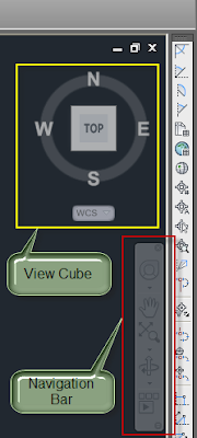
One of the first new things I noticed when I opened Civil 3D 2011 this week was the View Cube and Navigation Bar. While the View Cube is a really cool and useful tool, I don't use it the majority of the time, especially in a 2D view, so for me it's just taking up screen space.
To figure out how to hide this thing (since I couldn't find an X to close it), I searched in the System Variables dialog box for a command to change the view options for this object. You can find the System Variable dialog box in the Tools panel on the Express Tools ribbon tab. I scrolled through the list looking for likely suspects and found some variables beginning with NAV.
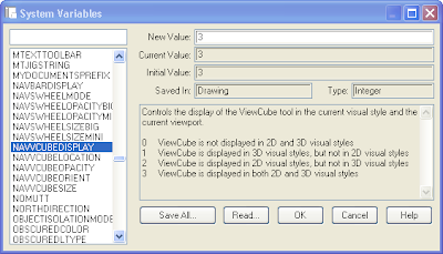
If you select one of the system variables in the list, you'll see a description of what that variable controls and the values that can be set including a description of each option. The Initial Value for NAVVCUBEDISPLAY is 3. That means it is visible in both 2D and 3D visual styles. I figure I only want it to be visible in 3D visual styles so I need to change the New Value to 1 then select OK.
There is also a Navigation Bar that is visible just below the View Cube. You can access the View Cube, the Wheel, Pan, Zoom commands, Orbit commands, and Show Motion in this Navigation Bar. The Navigation Bar and View Cube both have transparency settings that you can control so that you can still see drawing objects behind the tool, you just can't select an object at a location that is within the bounds of the Navigation Bar or the View Cube, for example.
If you view your drawings from multiple views such as Top, Front, SW Isometric, etc., keep this View Cube visible and use it. It works very well and is intuitive to use. If you only draw in 2d or might view something in 3d maybe twice a year, then maybe you should go ahead and change the NAVVCUBEDISPLAY value to 0 or 1.
The Navigation Bar has a very small x in the top right corner that can be used to close the toolbar. You can also change the NAVBARDISPLAY system variable to 0 to hide it.
In summary:
NAVBARDISPLAY = 0 (don't display the Navigation Bar)
NAVBARDISPLAY = 1 (display the Navigation Bar)
NAVVCUBEDISPLAY = 0 (don't display the View Cube)
NAVVCUBEDISPLAY = 1 (display the View Cube only in 3D visual styles)
NAVVCUBEDISPLAY = 2 (display the View Cube only in 2D visual styles)
NAVVCUBEDISPLAY = 3 (display the View Cube in 2D and 3D visual styles)
One more thing before you go:
The settings I described in this post are drawing specific, so be sure and set them to your preferred setting in all your templates. You might even want the View Cube visible in some templates (such as those with surfaces or 3D objects), but not others (such as plan view only drawings). Thankfully, Autodesk gave us not only a great tool, but also flexibility with the view settings so let's use them as they were intended.

One of the first new things I noticed when I opened Civil 3D 2011 this week was the View Cube and Navigation Bar. While the View Cube is a really cool and useful tool, I don't use it the majority of the time, especially in a 2D view, so for me it's just taking up screen space.
To figure out how to hide this thing (since I couldn't find an X to close it), I searched in the System Variables dialog box for a command to change the view options for this object. You can find the System Variable dialog box in the Tools panel on the Express Tools ribbon tab. I scrolled through the list looking for likely suspects and found some variables beginning with NAV.

If you select one of the system variables in the list, you'll see a description of what that variable controls and the values that can be set including a description of each option. The Initial Value for NAVVCUBEDISPLAY is 3. That means it is visible in both 2D and 3D visual styles. I figure I only want it to be visible in 3D visual styles so I need to change the New Value to 1 then select OK.
There is also a Navigation Bar that is visible just below the View Cube. You can access the View Cube, the Wheel, Pan, Zoom commands, Orbit commands, and Show Motion in this Navigation Bar. The Navigation Bar and View Cube both have transparency settings that you can control so that you can still see drawing objects behind the tool, you just can't select an object at a location that is within the bounds of the Navigation Bar or the View Cube, for example.
If you view your drawings from multiple views such as Top, Front, SW Isometric, etc., keep this View Cube visible and use it. It works very well and is intuitive to use. If you only draw in 2d or might view something in 3d maybe twice a year, then maybe you should go ahead and change the NAVVCUBEDISPLAY value to 0 or 1.
The Navigation Bar has a very small x in the top right corner that can be used to close the toolbar. You can also change the NAVBARDISPLAY system variable to 0 to hide it.
In summary:
NAVBARDISPLAY = 0 (don't display the Navigation Bar)
NAVBARDISPLAY = 1 (display the Navigation Bar)
NAVVCUBEDISPLAY = 0 (don't display the View Cube)
NAVVCUBEDISPLAY = 1 (display the View Cube only in 3D visual styles)
NAVVCUBEDISPLAY = 2 (display the View Cube only in 2D visual styles)
NAVVCUBEDISPLAY = 3 (display the View Cube in 2D and 3D visual styles)
One more thing before you go:
The settings I described in this post are drawing specific, so be sure and set them to your preferred setting in all your templates. You might even want the View Cube visible in some templates (such as those with surfaces or 3D objects), but not others (such as plan view only drawings). Thankfully, Autodesk gave us not only a great tool, but also flexibility with the view settings so let's use them as they were intended.
Wednesday, March 24, 2010
To Fade or Not to Fade...That Might Be Your Question
As I work with a new group of Civil 3D users, I find that some of the new AutoCAD 2010 commands and settings have not been made clear to CAD users at all companies. This week I was able to share XDWGFADECTL with my fellow employees. In case you're in the dark about this command as well, here's the scoop:
One of the things I notice when setting up AutoCAD 2010 or Civil 3D 2010 on a new computer is that drawings containing xreferenced drawings don't look the same as they did when I opened them in previous versions of AutoCAD. Now I'm not talking about having different colors for layers. You can check the layers and you'll still see red, yellow, green, etc. However, an object in the current drawing on a layer that's green looks different from an object in an xreferenced drawing that is also on a layer that's green. Here's an example of what you see with a black model space background:

It does make it very clear what is in the xreferenced drawing and what is in the current drawing, but it can be a bit difficult to see the objects in the xreferenced drawing with a black background such as this. Here are two ways to change this setting.
The first method is to type XDWGFADECTL at the command prompt and set it to 0 (zero) if you want xref objects to appear without fading as seen in previous versions of AutoCAD or Civil 3D.
The second method is through the System Variable Editor:
In the default Civil 3D workspace of Civil 3D 2010, select the "Express Tools" ribbon tab.
Now left click on the System Variable Editor icon.
Once the System Variable Editor dialog box opens, scroll down the list of variables and left click on XDWGFADECTL. The Initial Value is 70 and the Current Value will probably be 70 as well.
Left click in the white box labeled New Value.
Change the value to 0 (zero), but DON'T PRESS ENTER.
Left click on another system variable in the list such as XFADECTL, then left click back on XDWGFADECTL. The New Value should still be set to 0 (zero).
Now left click on the OK command button.
Here's the same text after changing this system variable:
NOTE: This system variable has settings other than a simple "on" and "off" setting. Here's a description and valid values for the XDWGFADECTL system variable:
The XDWGFADECTL system variable controls the dimming for all DWG xref objects. The valid XDWGFADECTL system variable value is between -90 and 90.
When the value is 0 (zero), DWG xref objects are not faded.
When the value is positive, controls the percent of fading up to 90 percent.
When the value is negative, xref objects are not faded, but the value is saved for switching to that value by changing the sign.
One of the things I notice when setting up AutoCAD 2010 or Civil 3D 2010 on a new computer is that drawings containing xreferenced drawings don't look the same as they did when I opened them in previous versions of AutoCAD. Now I'm not talking about having different colors for layers. You can check the layers and you'll still see red, yellow, green, etc. However, an object in the current drawing on a layer that's green looks different from an object in an xreferenced drawing that is also on a layer that's green. Here's an example of what you see with a black model space background:

It does make it very clear what is in the xreferenced drawing and what is in the current drawing, but it can be a bit difficult to see the objects in the xreferenced drawing with a black background such as this. Here are two ways to change this setting.
The first method is to type XDWGFADECTL at the command prompt and set it to 0 (zero) if you want xref objects to appear without fading as seen in previous versions of AutoCAD or Civil 3D.
The second method is through the System Variable Editor:
In the default Civil 3D workspace of Civil 3D 2010, select the "Express Tools" ribbon tab.
Left click in the white box labeled New Value.
Change the value to 0 (zero), but DON'T PRESS ENTER.
Left click on another system variable in the list such as XFADECTL, then left click back on XDWGFADECTL. The New Value should still be set to 0 (zero).
Now left click on the OK command button.
Here's the same text after changing this system variable:
NOTE: This system variable has settings other than a simple "on" and "off" setting. Here's a description and valid values for the XDWGFADECTL system variable:The XDWGFADECTL system variable controls the dimming for all DWG xref objects. The valid XDWGFADECTL system variable value is between -90 and 90.
When the value is 0 (zero), DWG xref objects are not faded.
When the value is positive, controls the percent of fading up to 90 percent.
When the value is negative, xref objects are not faded, but the value is saved for switching to that value by changing the sign.
Subscribe to:
Posts (Atom)


