Showing posts with label Points. Show all posts

Monday, March 28, 2016

Point to Point Inverse in Civil 3D

I find that map commands in Civil 3D can be very useful for both land surveyors and civil engineering technical staff. The problem seems to be that many users don't know about these very useful commands.

Here's a question than I'm often asked by land surveyors:
Is there a point to point inverse in Civil 3D?

The answer to this question is YES!
CGSLIST + the 'PN transparent command.

CGSLIST

CGSLIST is located on the Analyze ribbon tab in the Inquiry panel.


BEFORE YOU BEGIN

The help information for this command doesn't mention vertical difference, but that information is included in the output for this command.


This command uses the settings for Angle, Distance, and Direction that are stored in the Ambient Settings of the current drawing. If you want the course (bearing) to be in N90°00'00"E format, open the Drawing Settings dialog, choose the Ambient Settings tab, change the Direction > Format setting to DD°MM'SS" and press OK. You can also change the precision for coordinates, distances, and more.


You should also expand the command line so that you can see at least five lines of the command line history.


My example begins with a drawing that contains two points that are exactly 10 feet apart horizontally and 5 feet apart vertically. This allows me to confirm the horizontal and vertical results of the command.

Using the CGSLIST Command

  1. After selecting the Analyze ribbon tab, locate the Inquiry panel and click on the List Slope (CGSLIST) icon.


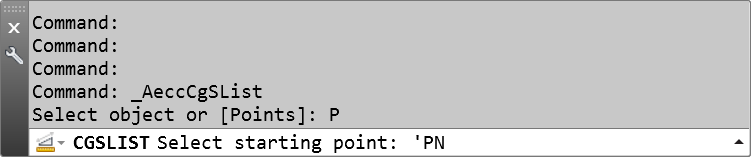
  2. When prompted, type P and press enter to use the Points selection option. Selecting the Points option here only notifies the command that you want to select coordinate points, not Civil 3D cogo points, for the input data type. 
  3.  

    NOTE: The command line shows that _AeccCgSList is the command running. You can also access this command by typing CGSLIST at the command line and pressing enter. If you are using Map 3D, use MAPCGSLIST. All three commands work in Civil 3D version 2015 or later. 

  4. When prompted to select a starting point, type 'PN and press enter. This will tell the command that you will be entering Civil 3D cogo point numbers instead of selecting coordinate points by clicking on the screen.


  5. When prompted to enter a point number, enter the starting cogo point number then press enter.


  6. The coordinates of the cogo point will appear in the command line history. Now enter the next cogo point number for the ending point then press enter.


  7. This command reports horizontal distance and elevation difference. It also reports the point elevations along with the grade and slope between the points. Notice that the distance shown is a horizontal distance, not a slope distance which is the result reported when using the DISTANCE or MEASUREGEOM command.

Now...
Don't be fooled!

Even though the command shows that the 'PN transparent command is still running, the CGSLIST command has reverted to the original Select object or [Points] prompt. At this point you'll need to press ESC to exit the 'PN transparent command, type P then enter to return to the Points selection, and finally type 'PN and press enter to return to the 'PN transparent command.

If you want a command that repeats with the 'PN transparent command, record a macro. If you're interested in a follow-up blog describing how to create and use that macro, please let me know in the comments section of this posting.

Friday, November 11, 2011

What's Missing In the World of Civil 3D Points? Not This!


Sure there are feature requests that we all have for Civil 3D points such as having full functionality of dynamic blocks within a point style, but this post is actually about what is no longer missing.


This morning I was asked how to find ranges of point numbers that were not currently being used in a drawing. In older versions of Civil 3D, one might have tried to look at the All Points point group properties for a list of points in that group. Well, now there's an easier way to get the answer.

Beginning with Civil 3D 2011, we were given this nifty new command:

LISTAVAILABLEPOINTNUMBERS

This command returns a list of point numbers that are not in use in the current drawing. Now you might be thinking that is a really long command name to remember but don't panic. Here's a how you can access the command:
  1. In Civil 3D 2011, at the command line, type LISTA then press tab then enter. Civil 3D will auto-complete the command for you.
  2. In Civil 3D 2012, at the command line, type LISTA then press enter (no tab key required). Civil 3D will auto-complete the command for you.
  3. In Civil 3D 2011 or 2012, select a Civil 3D point. On the COGO Point contextual ribbon tab, look for the COGO Point Tools panel . Left click on the bottom of that panel and a fly out will appear. Choose List Available Point Numbers from the list.


So now you know one thing that is no longer missing from the world of Civil 3D points.

Friday, May 6, 2011

Don't Forget These Commands...Part 1

There are so many commands in AutoCAD and Civil 3D that we use every day. Some of them are available via toolbars, menus, or the ribbon, that you only have to learn where to find them, not memorize them.

In my case, there are a few commands or system variables that just get lost in the deep void of space inside my brain. Here's a few of them:

LINEWORKSHRINKWRAP - Creates a boundary around a selection set of objects.

PELLIPSE - Setting this variable to 1 will draw an ellipse as a polyline.

FILEDIA - This variable gets set to 0 during some commands and/or lisp routines. If AutoCAD crashes, you may have to reset it to 1 to display dialog boxes instead of command line prompts.

'STAE - Transparent command for Civil 3D to select station from the parent alignment of a profile view.

'SSE - Transparent command for Civil 3D to select station from the parent alignment of a profile view and elevation from a surface.

'PSE - Transparent command for Civil 3D to select station and elevation from a profile view.

'ZTP - Transparent command for Civil 3D to zoom to a point or range of points.

There's plenty more to add to this list, but it's a start.

Tuesday, March 2, 2010

Why Do You Have To Be Different?

You may think I've dropped off the face of the planet, but I haven't. I'm happy to say that I've embarked on a new career and hopefully that means you, my blog readers, will be learning some new and helpful information in the process. I'll have to discuss my journey from Point A to Point B in another post because right now I have something to show you.

Monday, March 1, 2010, was my first day to officially work as a "Civil 3D Trainer" even though I'm been doing that type of work for years now. As one of my first troubleshooting activities, I was presented with a "problem tree" that wouldn't size correctly. Sounded like a interesting issue to me, so I met with the technician to see the problem firsthand.

The drawing consisted of an existing survey that included Civil 3D points. The marker symbol was not sizing correctly when compared to its peers. In this case, Tree #4987 was supposed to be a size "12", but it sure didn't look like the nearby size "12" Tree #5072.

"How did those tree symbols get placed in the drawing?" was my first question. I was told that the tree symbols were a part of the point style. Since all the other trees in the drawing looked correct given the tree diameter size, the problem must be something wrong with that individual point.

So what was wrong with Tree #4987? It was time to take a closer look at these two points by viewing them in the Point Editor Panorama. [You can access this view by selecting the two cogo points and then left clicking on the Edit/List Points in the Modify panel of the COGO Points Contextual menu.]


Here's the Panorama view (some columns were hidden for this image).:

As I reviewed the two points in the list (you may have to use the slider bar along the bottom of the Panorama View to see additional columns), I noticed that the X-Y Scale for the "good tree" point (#5072) was set to the tree diameter size of "12", but the X-Y Scale for the "problem tree" point (#4987) was blank. I suggested that the technician reset the X-Y Scale of tree point #4987 to 12 and the tree symbol for the "problem tree" was immediately updated and now matched the symbol size for Tree #5072.

Problem solved!

Despite how easy this solution may seem now, if you didn't setup your template or know the software well enough to know where to look for this solution, you can get real frustrated. Don't let yourself get too stressed about situations like this, just learn where to go for answers.

Answers can be found in places such as the Civil 3D help files, training manuals, your in-house Civil 3D Guru, discussion forums, Civil 3D Blogs, your Autodesk reseller (if you're on subscription), and you might even have to submit a request to Autodesk directly. If your area has a local Civil 3D User Group meeting, get contact info from the "Civil 3D Gurus" that you meet there. Sometimes it's knowing how to phrase the question or using the correct terminology.

There are so many resources available to us that we sometimes overlook. Be diligent and keep working at it. Civil 3D can work like a well oiled machine if you work with it, not against it.

Good luck with your next Civil 3D problem and use the resources you have available. Most of the time the answer is out there, somewhere, just waiting to be found.