Showing posts with label Templates. Show all posts

Monday, December 3, 2018

Convert Survey Figures to Polylines

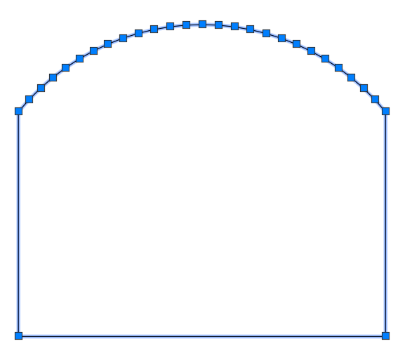
Sometimes survey figures are exactly what you want and other times you just want a polyline at elevation zero. If your like me, you created a figure style that flattens all elevations to zero then you exploded it. If that figure had an arcs, they became segmented like this:
I'm happy to report that there is a workflow to create these polylines with arcs from figures. I have confirmed that this workflow will work for versions 2016 through 2019. Note that the polylines will not update if the survey figure changes and is updated in the drawing.

Create a 2D figure style in your template

  1. In your template, expand the Toolspace > Settings tab > Survey > Figures category.
  2. Right click on Figure Styles and choose New.


  3. In the Figure Style dialog > Information tab, set the figure style name to 2D.


  4. In the Figure Style dialog > 3D Geometry tab, set the Figure display mode to Flatten figure to elevation and confirm that the Flatten figure to elevation is set to 0.00.


  5. In the Figure Style dialog > Display tab, change the layer, color, linetype, and so on to meet your CAD standards then click OK.
  6. Right click on the Toolspace > Settings tab > Survey category and choose Edit Feature Settings.


  7. In the Edit Feature Settings - Survey dialog, expand the Default Styles category and set the Default Figure Style to the 2D figure style you just created then click OK.


  8. Save and close the template.

Export Survey Figures to Polylines at Elevation Zero

  1. Begin a drawing with the template that contains the 2D figure style.
  2. Open a survey database and import figures to the drawing. The default style should be the 2D figure style.
  3. Set the UCS to World then save the drawing.
  4. In the application menu, select Export > Export Civil 3D Drawing.


      NOTE: Exploding figures using the 2D figure style will create polylines with segmented curves. That's why you'll need to use the Export Civil 3D Drawing command to get polylines with arcs.

  5. In the Export Autodesk Civil 3D Drawing dialog, choose the folder for the exported drawing then click Export.


  6. When the export is complete, click OK in the Export Status Dialog then Cancel in the Autodesk Civil 3D Drawing dialog.


  7. Open the exported drawing and confirm that the figures were exported to polylines at elevation zero.
  8. Select all the polylines representing exported figures and copy to the clipboard with a basepoint using SHIFT+CTRL+C and entering 0,0 as the base point.
  9. If you are replacing the figures in the original drawing, you can now delete them.
  10. In the original drawing, confirm that the UCS is set to World then use CTRL+V and enter 0,0 as the insertion point to paste the polylines into the correct location.
  11. Save the drawing.
An alternate workflow might be to have a separate template for importing just figures into a temp drawing so that you can export them and they will be on the correct layer. For this you'll need separate figure styles for each type of figure/layer combination you need. Then you can choose to import figures into the original base drawing onto the feature line or equivalent layer and have them displayed as a 3d object instead of a 2D object.

Monday, March 28, 2016

Point to Point Inverse in Civil 3D

I find that map commands in Civil 3D can be very useful for both land surveyors and civil engineering technical staff. The problem seems to be that many users don't know about these very useful commands.

Here's a question than I'm often asked by land surveyors:
Is there a point to point inverse in Civil 3D?

The answer to this question is YES!
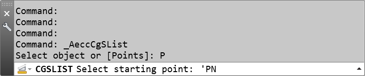
CGSLIST + the 'PN transparent command.

CGSLIST

CGSLIST is located on the Analyze ribbon tab in the Inquiry panel.


BEFORE YOU BEGIN

The help information for this command doesn't mention vertical difference, but that information is included in the output for this command.


This command uses the settings for Angle, Distance, and Direction that are stored in the Ambient Settings of the current drawing. If you want the course (bearing) to be in N90°00'00"E format, open the Drawing Settings dialog, choose the Ambient Settings tab, change the Direction > Format setting to DD°MM'SS" and press OK. You can also change the precision for coordinates, distances, and more.


You should also expand the command line so that you can see at least five lines of the command line history.


My example begins with a drawing that contains two points that are exactly 10 feet apart horizontally and 5 feet apart vertically. This allows me to confirm the horizontal and vertical results of the command.

Using the CGSLIST Command

  1. After selecting the Analyze ribbon tab, locate the Inquiry panel and click on the List Slope (CGSLIST) icon.


  2. When prompted, type P and press enter to use the Points selection option. Selecting the Points option here only notifies the command that you want to select coordinate points, not Civil 3D cogo points, for the input data type. 
  3.  

    NOTE: The command line shows that _AeccCgSList is the command running. You can also access this command by typing CGSLIST at the command line and pressing enter. If you are using Map 3D, use MAPCGSLIST. All three commands work in Civil 3D version 2015 or later. 

  4. When prompted to select a starting point, type 'PN and press enter. This will tell the command that you will be entering Civil 3D cogo point numbers instead of selecting coordinate points by clicking on the screen.


  5. When prompted to enter a point number, enter the starting cogo point number then press enter.


  6. The coordinates of the cogo point will appear in the command line history. Now enter the next cogo point number for the ending point then press enter.


  7. This command reports horizontal distance and elevation difference. It also reports the point elevations along with the grade and slope between the points. Notice that the distance shown is a horizontal distance, not a slope distance which is the result reported when using the DISTANCE or MEASUREGEOM command.

Now...
Don't be fooled!

Even though the command shows that the 'PN transparent command is still running, the CGSLIST command has reverted to the original Select object or [Points] prompt. At this point you'll need to press ESC to exit the 'PN transparent command, type P then enter to return to the Points selection, and finally type 'PN and press enter to return to the 'PN transparent command.

If you want a command that repeats with the 'PN transparent command, record a macro. If you're interested in a follow-up blog describing how to create and use that macro, please let me know in the comments section of this posting.

Thursday, December 20, 2012

Which Way is North?

 Okay I admit it, the allure of one day being invited into the "Autodesk Expert Elite Program" has me checking the Autodesk Civil 3D Discussion Forums and blogging again. Since I'm only at the designated level of "Active Contributor", I have some work to do. Thanks, Autodesk!

The idea behind this post came from a question on the Autodesk Civil 3D Discussion Forums here. The issue is with a Civil 3D 2013 Dynamic North Arrow that is associated with a viewport with the UCS set to World, the dview twist angle set to "0", and the viewport set to plan. For some reason the north arrow was off by over 4.6 degrees. Bruce, a designated Autodesk "Expert Elite" himself, was kind enough to post a sample drawing to show the issue and here's what was discovered.:

Dynamic north arrows are associated with the 
selected coordinate system in the Units and Zone tab.

When you place a dynamic north arrow in a layout and associate it with a viewport, the block reads the current coordinate system that is assigned in the drawing settings Units and Zone tab and adjusts the default rotation of the block based on that setting. Even if there isn't a rotation in the viewport, the north arrow won't be pointing due north as you might expect. Here's an example.:

  1. In Civil 3D 2013, open an existing drawing or create a new drawing from scratch.
  2. On the model tab (modelspace) draw a rectangle of any size.
  3. In the Settings tab of Toolspace, right click on the drawing name and choose Edit Drawing Settings.
  4. On the Units and Zone tab, set the Drawing Settings Zone Categories to No Datum, No Projection.

    No Datum, No Projection

  5. In a layout (paperspace), create a rectangular viewport from scratch. Make sure you can see the rectangle in the viewport to verify rotation throughout this example. You may need to zoom out if necessary to see the rectangle rotation better.
  6. When you are in paperspace, there should be a Layout Tools ribbon tab available. Locate the Layout Elements Panel and select one of the built-in dynamic north arrows to place in the drawing.

    Select one of the built-in Dynamic North Arrows

  7. When prompted at the command line, select a viewport for the north arrow association.
  8. Next you'll be prompted to select a location to place the north arrow.
  9. The north arrow may be very small and hard to see. Set the x, y, and z scales to 20. Notice that it appears to be pointing due north when compare to the rectangle in the viewport.

    North is North
  10. To make sure we compare apples to apples, make a copy of the viewport in your drawing.
  11. Back in the Toolspace, Settings, Drawing Settings, Units and Zone tab, set the selected coordinate system to WA83-SF, then OK.
  12. Now place a new dynamic north arrow in the drawing using the second viewport (the copy) for the north arrow association. (Only one dynamic north arrow can be assigned to each viewport.)
  13. Place the second north arrow near the first one and again set the x, y, and z scales to 20.
  14. Notice that the north arrows don't point the same direction? That's because of the change made to the selected coordinate system.

    Compare the Dynamic North Arrows
This is definitely something that you need to take into consideration when you use the dynamic north arrows in a drawing with an assigned coordinate system other than No Datum, No Projection. If you do need to rotate the contents of a viewport, just set the coordinate system back to No Datum, No Projection before making the change, then reset the coordinate system as needed.

Another consideration is to set the coordinate system in the base drawing and attach it to a separate sheet drawing for plotting. The sheet doesn't need a coordinate system assigned to it so there won't be a discrepancy between plan north and the rotation of the dynamic north arrow.

UPDATE:  There is another solution that actually works better.

GEOGRAPHICLOCATION

In modelspace, type GEO at the command line then choose Remove the geographic location.


With the geographic location removed, you can keep the coordinate system assigned and the dynamic north arrow will point plan north as expected.

Tuesday, December 11, 2012

Slow Down and Render This

Yesterday, I received an email with an attached drawing. Verbally, the request was to determine why the drawing is so slow, especially when using the zoom extents.The email included the following additional information:

This file was messing up badly on Wednesday...crazy slow, etc.

This morning with my new reload of AutoCAD 2011, it wasn't as bad... but still has signs of corruption...


One thing that I noticed is that the TIN in the V-TINN-VIEW layer doesn't look right... the contours are fine... but I didn't know if you had a fix for that...


There are lots of things that can cause a drawing to be a little slow. I have a list of things I check in a drawing but I knew that many of those had already been checked by the owner of this drawing. The comment about the TIN not looking correct was definitely a clue to the problem as was the knowledge that the user had recently been working with point clouds including some third party software.

I knew the fresh install and absence of the third party software had ruled out that being the issue so my first option was simply to open the drawing. Here's what I saw in the bottom left corner of the application:

This is not the ucs icon that I typically see in my drawings. The thickness of the ucs icon elements was an indication to me that the visual style was set to something other than 2D Wireframe.

To verify my suspicion, on the View ribbon tab, I selected the dropdown on the Views Panel and found the visual style was set to Hidden.


 I left clicked on the Hidden visual style and changed the visual style to 2D Wireframe.


Now the ucs icon looks as expected and the speed of the drawing has returned to "normal".


Now if you are using AutoCAD 2012 or later, take a look at the upper left corner of model space. There you should find the Visual Style Controls.


As you can see, the visual style in this drawing is now set to 2D Wireframe. Changing this setting from Hidden to 2D Wireframe greatly improved the speed of the drawing.

Wednesday, December 14, 2011

Don't Forget These Commands...Part 4

Here's another system variable that I forget because I only seem to need it when working on drawings from others:

XCLIPFRAME

Here's the definition from the AutoCAD Help Menu:


When this system variable is set to 0 and you xclip an xreference drawing, you can't see the boundary of the xclip and therefor you can't invert the selection. We set this variable to 2 in our templates so that we can see the frame (for adjusting and inverting as needed), but the frame won't plot.

Tuesday, December 13, 2011

Quick Tip about Importing Styles and Settings


If you're using Civil 3D 2012, you've hopefully already heard about the ability to Import Styles and Settings. This new command is a real time saver but be careful, because you may not be getting everything you want.

Here are a few things you won't get by using the Import Styles Command:

  • Object Layer Settings (Use this workaround to transfer the settings to your current drawing)
  • Blocks and Layers not used in styles (Use Design Center to import all layers and blocks)
  • Description Key (Use old style drag & drop to import into your current drawing)
  • Parts Lists (Use old style drag & drop to import into your current drawing)
There may be more items that aren't imported, but those three items will definitely be missing if you use the Import Styles command.

Feel free to add comments for additional items that you find missing when you use the command.

Added Parts Lists per TimStalin's comment.

Wednesday, September 14, 2011

Get Those Child Styles Under Control

Have you ever created a child style, changed a setting on it, then wished that component property was still following the default setting from the parent style? This is especially apparent when changes are made to the Text Contents of a component. Before you go blaming the software for not working correctly, take a look at the style itself. It may be doing exactly what you told it to do.

Once you make a change to any part of a component of a style, an override is flagged on the Summary tab and that part of the component will no longer follow the changes made to the parent style. Here's a short exercise to show how it works:
  1. Create a new drawing from the "_AutoCAD Civil 3D (Imperial) NCS template" in Civil 3D 2012.
  2. In the Toolspace, Settings tab, locate the Structure Label Styles.


  3. Expand the Label Styles and select the label style named "Data with Connected Pipes (Sanitary)", right click, and choose Edit... from the list.


  4. After the Label Style Composer dialog box is open, select the Layout tab and verify that there are three components in this style: Structure Text, Incoming Pipes, and Outgoing Pipes.


  5. Now close this dialog box by left clicking on Cancel.
  6. Locate the Structure Label Style in the Toolspace Settings tab again. This time right click on the "Data with Connected Pipes (Sanitary)" style and choose "New..." from the list.


    This will create a child style of the selected label style.
  7. In the Label Style Composer dialog box, select the Information tab and edit the Name to: "Data with Connected Pipes (Sanitary) [Description Only]". You can also edit the Description for this label style on the Information tab at this time.
  8. Now select the Layout tab, then in the Component name: dropdown list, select "Incoming Pipes".


  9. Under the "General" section, locate the "Visibility" property . Change the value to False.


  10. Repeat this process for the Outgoing Pipes component too.
  11. Now select the Summary tab. In the Property column, left click on the by Component 2 to expand the properties of that component. 
In the Override column there should be a green check mark in the box in the General: Visiblity row. This means that even if you change this visibility state in the parent style, such as setting the value to False, the visibility state of this component will not change. There should be a green check mark in the box in the General: Visibility row of Component 3 as well. Left click on OK to complete these changes to the style.

Now to see how this change affects the parent style, edit the original label style. You can do this by repeating Step 3, then selecting the Summary tab. Left click on the by Component 2 and you'll see a gray arrow pointing down in the Child Override column. This indicates that this property has been overridden in at least one child style. If you want to remove this override from all the child styles, left click on the gray arrow. A small red x will appear near the bottom right side of the gray arrow to indicate that you will be removing these overrides. Left click on Apply. The Summary tab will refresh at this point and all expanded properties will collapse. Left click on the by Component 2 again and there should no longer be a gray arrow in the Child Override column of the General: Visibility row. You can edit the child style to verify that the Visibility of Component 2 was reset to True.

The point of this exercise was to show you how and when the overrides are created so that if your child style isn't responding the way you expect when a change is made to the parent style, take a look at the Summary tab and look for Overrides.

Friday, May 27, 2011

Out With the Old, In With the New

While reading discussions on the LinkedIn AutoCAD Civil 3D Users Group, I began typing this response that I later decided was worth sharing with others.

The discussion was on why firms are still using LDD instead of Civil 3D. The responses are typically:
  1. cost of training
  2. no time to learn it
  3. "if it ain't broke, don't fix it" attitudes
  4. lack of initiative to make it happen
At the firms where I've been employed, I've seen several of these responses. It seems that because an individual knows exactly what workflow to use, then it must be the most efficient one. However, once the employee has learned how to use Civil 3D and begins to become efficient at it, they may actually dread going back to LDD to work on an old project.

Learning Civil 3D takes either enthusiasm to learn and embrace new software or a mandate from management to learn it. My current firm mandated the change and now my coworkers actually request making the change from LDD to Civil 3D on projects whenever possible. In fact, just last week I helped a coworker use Civil 3D to do something with surfaces that he was unable to do in LDD. Using LandXML and drawing objects, the procedure was done very efficiently in Civil 3D yet the final product is still in the original LDD project file format.

For Civil 3D, there are so many training aids available (many of them free, especially if you are on subscription) including a Home Use License, Autodesk University recorded videos and handouts, subscription training videos, YouTube, etc.

For me to learn Civil 3D, after a couple of employer paid training classes, I requested a Civil 3D Home Use License from the company's Autodesk contract administrator and spent hours learning to create a project from scratch with Civil 3D. Of course the time I spent at home was not paid, but it gave me an opportunity to learn the software better than anyone else at the company. Now with Civil 3D experience being a more valuable commodity in the workplace, the time I spent unpaid was well worth it. Also, the fact that I learned it before more and more features were added helped a lot too. Instead of learning EVERYTHING at once, I learned alignments, then profiles. Next I tackled surfaces, then pipes, etc. I suggest you do the same thing to learn the software. Don't try to swallow the whole bottle at once, it can be overwhelming. Take smaller bites and see how they taste.

Workflows for Civil 3D are so different than LDD. Until you can put that mentality aside, you will struggle to learn the software. As for the software not doing what you want from a surveying or civil engineering perspective, join the Autodesk beta testing community or post your feature request to the Civil 3D wish list on the AUGI forums. Not using the software because a feature doesn't exist won't get that feature there any faster. Besides, the feature may be there just in a different format than where you expect. This is where local Civil 3D User Groups or discussion forums can be a great asset.

As a great man I know once said, "Don't give me problems, give me solutions!" I think we should all take this approach more, so here's my possible solution for you:

First get a copy of the software to begin your training. Download Civil 3D from the Autodesk website and begin your 30 day product trial or request a Home Use License from your contract administrator if you are on subscription. Of course you'll need a computer that can run Civil 3D. If that isn't a possibility, set aside a few hours a week to stay late, arrive early, or train through your lunch hour on your work computer.

Start with an existing project. Begin creating that project from scratch. This way you're not facing deadlines or trying to learn the software and design at the same time. Get the whole team together and work through issues of how to complete a particular task. Watch some training videos at home after you put the kids to bed. Take notes then duplicate the procedures at lunch the next day.

Another thing that will help with implementation of Civil 3D is to create templates for your firm. Yes, there's an NCS standard template that's provided with Civil 3D out of the box, but let's face it, there's not a single box of chocolates that pleases everyone and templates are no different.

Create a CAD standard and setup your templates to implement those CAD standards. If you get rid of some of the up front work, you'll be surprised how much easier it is for users to become efficient with the software and comply with CAD standards at the same time.

Here's an example: Our firm has a template setup just for existing utilities. It already contains pipe networks for each existing utility with all defaults set. You can be up and running and creating pipes and structures with this file in minutes. You don't have to go through the trouble of setting up the pipe network parts list, the pipe network itself, the default layer names, default pipe and structure names, default pipe and structure styles and labels, etc. It's incredible how much time this will save you and how much you don't have to know about using the software because it's already done for you.

Here are a few more suggestions for learning to use Civil 3D:
  1. First of all USE THE SOFTWARE! If management provides training and you don't use the software, then you're probably going to struggle to remember what you learned.
  2. If you don't have time to create templates yourself, then pay someone to do it for you.
  3. Set deadlines then enforce them. Request a progress set on the pilot project as if it were a real project.
  4. Work with your employees to get the most from them. Offer an incentive to completing their first project using Civil 3D.

I think many firms overlook the value of using the current software as a tool instead of as a crutch. Don't be one of those firms!
Tuesday, August 31, 2010

Transfer Object Layer Settings Between Drawings

I found a nice "undocumented feature" in Civil 3D 2011 today. I found this totally by accident and though I lost a couple of minutes worth of changes to a template, I know that this find will save me a lot of time in the future, especially when a drawing is started from the wrong template.

One of the frustrating things about working with old drawings is that everything gets placed on Layer 0. Some of this can be corrected by using commands such as AECIMPORTSTYLES and AECCIMPORTSTYLESANDSETTINGS as posted by Scott McEachron of the I.II.I consortium. I haven't had great success with those commands yet, but as Scott stated, the commands are undocumented and unsupported.

Well here's another undocumented and unsupported feature (some might even call it a bug):

You can copy the Object Layers settings from one drawing to another...in seconds...FOR FREE! Want to know how? Here you go:

Before you begin, I will state that I'm using Civil 3D 2011 on the Windows 7 64-bit OS. I can't guarantee that it will work on older versions of Civil 3D or on a different OS.
  1. Create a drawing from a template that contains the correct Object Layer settings. I'll call this drawing "TEMPLATE".
  2. Now open a drawing that doesn't have the correct Object Layer settings. I'll call this drawing "BLANK".
  3. Make Toolspace visible (type showts at the command line or locate the toolspace button on the Home Tab of the ribbon).
  4. Select the Settings tab on the Toolspace palette.
  5. Set the view dropdown to Master View.
  6. Make sure that the "BLANK" drawing is current (it's shown at the top of the list in the Settings tab).
  7. Now scroll down until you see the "TEMPLATE" drawing in the Settings tab.
  8. With your cursor positioned over the "TEMPLATE" drawing name, right click and select Edit Drawing Settings... from the list.
  9. Select the Object Layers tab and verify that these are the object layers that you want used in the "BLANK" drawing.
  10. Now all you have to do is left click on OK.
Voila! You have just changed all the default Object Layers in your current drawing, "BLANK", to those in the "TEMPLATE" drawing. Feel free to check for yourself.

I'm interested in hearing if this trick works on older versions of Civil 3D and/or other operating systems, both 32-bit and 64-bit so please leave me a comment.

Wednesday, April 21, 2010

Navigate This You View Cube

I know my first post about Civil 3D 2011 shouldn't be about how to hide one of the new features, but it's going to be posted by somebody so here you go:


One of the first new things I noticed when I opened Civil 3D 2011 this week was the View Cube and Navigation Bar. While the View Cube is a really cool and useful tool, I don't use it the majority of the time, especially in a 2D view, so for me it's just taking up screen space.

To figure out how to hide this thing (since I couldn't find an X to close it), I searched in the System Variables dialog box for a command to change the view options for this object. You can find the System Variable dialog box in the Tools panel on the Express Tools ribbon tab. I scrolled through the list looking for likely suspects and found some variables beginning with NAV.


If you select one of the system variables in the list, you'll see a description of what that variable controls and the values that can be set including a description of each option. The Initial Value for NAVVCUBEDISPLAY is 3. That means it is visible in both 2D and 3D visual styles. I figure I only want it to be visible in 3D visual styles so I need to change the New Value to 1 then select OK.

There is also a Navigation Bar that is visible just below the View Cube. You can access the View Cube, the Wheel, Pan, Zoom commands, Orbit commands, and Show Motion in this Navigation Bar. The Navigation Bar and View Cube both have transparency settings that you can control so that you can still see drawing objects behind the tool, you just can't select an object at a location that is within the bounds of the Navigation Bar or the View Cube, for example.

If you view your drawings from multiple views such as Top, Front, SW Isometric, etc., keep this View Cube visible and use it. It works very well and is intuitive to use. If you only draw in 2d or might view something in 3d maybe twice a year, then maybe you should go ahead and change the NAVVCUBEDISPLAY value to 0 or 1.

The Navigation Bar has a very small x in the top right corner that can be used to close the toolbar. You can also change the NAVBARDISPLAY system variable to 0 to hide it.

In summary:

NAVBARDISPLAY = 0 (don't display the Navigation Bar)
NAVBARDISPLAY = 1 (display the Navigation Bar)

NAVVCUBEDISPLAY = 0 (don't display the View Cube)
NAVVCUBEDISPLAY = 1 (display the View Cube only in 3D visual styles)
NAVVCUBEDISPLAY = 2 (display the View Cube only in 2D visual styles)
NAVVCUBEDISPLAY = 3 (display the View Cube in 2D and 3D visual styles)

One more thing before you go:
The settings I described in this post are drawing specific, so be sure and set them to your preferred setting in all your templates. You might even want the View Cube visible in some templates (such as those with surfaces or 3D objects), but not others (such as plan view only drawings). Thankfully, Autodesk gave us not only a great tool, but also flexibility with the view settings so let's use them as they were intended.

Sunday, April 27, 2008

How Many Inches in a Meter?

I know that the easiest way to convert your existing template to a new version of Civil 3D is to just open and save the template. However, you will be missing some of the new settings that just got implemented into the new version of the software.

One of these new settings can be found in the Drawing Settings dialog box, Units and Zone tab. There is a new "Imperial to Metric conversion" setting there. It defaults to "International Foot(1 Foot = 0.3048 Meters)" for the OOTB templates. This means that when you open and save your existing template, it will also be set to "International Foot".

So depending on your location and project, you might need to change this setting to "US Survey Foot(39.37 Inches per Meter)".


Although it could be found in previous versions, you may not know that there is a similar setting in the Land XML export settings under the Data Settings properties.