When working in the civil engineering world, you sometimes need to round a number up. For example, if you're looking to size circular rcp storm sewer, then you will need to be able to round to the nearest half foot. When working in Excel, the formula =ROUND(Number, Num_digits) will not give you the desired result.
So instead you should use the Excel CEILING function =CEILING(Number, Significance). The Ceiling function allows you dictate your rounding to the nearest multiple of significance.
In the case of a value of 3.298 feet that needs to be rounded up to the nearest 0.5 feet, we would use the formula =CEILING(3.298,0.5) to return a value of 3.5. Likewise a value of 2.033 would return a value of 2.5.
This great tip was provided by Steve Zobal, a coworker of mine at MWM DesignGroup.
Showing posts with label Pipes. Show all posts
Showing posts with label Pipes. Show all posts
Thursday, November 3, 2011


Wednesday, September 14, 2011
Get Those Child Styles Under Control
Have you ever created a child style, changed a setting on it, then wished that component property was still following the default setting from the parent style? This is especially apparent when changes are made to the Text Contents of a component. Before you go blaming the software for not working correctly, take a look at the style itself. It may be doing exactly what you told it to do.
Once you make a change to any part of a component of a style, an override is flagged on the Summary tab and that part of the component will no longer follow the changes made to the parent style. Here's a short exercise to show how it works:
Now to see how this change affects the parent style, edit the original label style. You can do this by repeating Step 3, then selecting the Summary tab. Left click on the by Component 2 and you'll see a gray arrow pointing down in the Child Override column. This indicates that this property has been overridden in at least one child style. If you want to remove this override from all the child styles, left click on the gray arrow. A small red x will appear near the bottom right side of the gray arrow to indicate that you will be removing these overrides. Left click on Apply. The Summary tab will refresh at this point and all expanded properties will collapse. Left click on the by Component 2 again and there should no longer be a gray arrow in the Child Override column of the General: Visibility row. You can edit the child style to verify that the Visibility of Component 2 was reset to True.
The point of this exercise was to show you how and when the overrides are created so that if your child style isn't responding the way you expect when a change is made to the parent style, take a look at the Summary tab and look for Overrides.
Once you make a change to any part of a component of a style, an override is flagged on the Summary tab and that part of the component will no longer follow the changes made to the parent style. Here's a short exercise to show how it works:
- Create a new drawing from the "_AutoCAD Civil 3D (Imperial) NCS template" in Civil 3D 2012.
- In the Toolspace, Settings tab, locate the Structure Label Styles.

- Expand the Label Styles and select the label style named "Data with Connected Pipes (Sanitary)", right click, and choose Edit... from the list.

- After the Label Style Composer dialog box is open, select the Layout tab and verify that there are three components in this style: Structure Text, Incoming Pipes, and Outgoing Pipes.

- Now close this dialog box by left clicking on Cancel.
- Locate the Structure Label Style in the Toolspace Settings tab again. This time right click on the "Data with Connected Pipes (Sanitary)" style and choose "New..." from the list.

This will create a child style of the selected label style. - In the Label Style Composer dialog box, select the Information tab and edit the Name to: "Data with Connected Pipes (Sanitary) [Description Only]". You can also edit the Description for this label style on the Information tab at this time.
- Now select the Layout tab, then in the Component name: dropdown list, select "Incoming Pipes".

- Under the "General" section, locate the "Visibility" property . Change the value to False.

- Repeat this process for the Outgoing Pipes component too.
- Now select the Summary tab. In the Property column, left click on the by Component 2 to expand the properties of that component.


Now to see how this change affects the parent style, edit the original label style. You can do this by repeating Step 3, then selecting the Summary tab. Left click on the
by Component 2 and you'll see a gray arrow pointing down in the Child Override column. This indicates that this property has been overridden in at least one child style. If you want to remove this override from all the child styles, left click on the gray arrow. A small red x will appear near the bottom right side of the gray arrow to indicate that you will be removing these overrides. Left click on Apply. The Summary tab will refresh at this point and all expanded properties will collapse. Left click on the by Component 2 again and there should no longer be a gray arrow in the Child Override column of the General: Visibility row. You can edit the child style to verify that the Visibility of Component 2 was reset to True.The point of this exercise was to show you how and when the overrides are created so that if your child style isn't responding the way you expect when a change is made to the parent style, take a look at the Summary tab and look for Overrides.
Tuesday, September 13, 2011
Multiple Surface Dilemma (Part 3)
NOTE: This is Part 3 of the Multiple Surfaces Dilemma Series. You can view Part 1 of the series here. In Part 1 of this series, a surface named ComboSurface was created. Make sure
you create that surface in your drawing before proceeding with these
steps.
Wouldn't it be nice to have a visual representation of the target minimum depth in the profile view while you're designing your pipe network? Here's a way to make that happen:
Create a new surface in your current drawing and name it "MinimumDepth". You can use the same procedure as described for creating the "ComboSurface" in the original post of this series. Just as with the ComboSurface, this surface will not need to be displayed so set the surface style to "_No Display" as it's created.
To add some substance to the new surface, you'll need to paste the ComboSurface into the MinimumDepth surface. Again, use the same procedure described in the original post of this series except you'll be pasting a different surface.
Under the MinimumDepth surface definition, locate the Edits option, right click, and select "Raise/Lower Surface".

When prompted at the command line, enter -4 to lower the MinimumDepth surface 4 feet.
The last thing to do is create a profile based on the MinimumDepth surface:

Wouldn't it be nice to have a visual representation of the target minimum depth in the profile view while you're designing your pipe network? Here's a way to make that happen:
Create a new surface in your current drawing and name it "MinimumDepth". You can use the same procedure as described for creating the "ComboSurface" in the original post of this series. Just as with the ComboSurface, this surface will not need to be displayed so set the surface style to "_No Display" as it's created.
To add some substance to the new surface, you'll need to paste the ComboSurface into the MinimumDepth surface. Again, use the same procedure described in the original post of this series except you'll be pasting a different surface.
Under the MinimumDepth surface definition, locate the Edits option, right click, and select "Raise/Lower Surface".
When prompted at the command line, enter -4 to lower the MinimumDepth surface 4 feet.
The last thing to do is create a profile based on the MinimumDepth surface:
- On the home ribbon tab, locate the "Create Design" Panel, left click on Profiles, then choose "Create Surface Profile" from the drop down list.
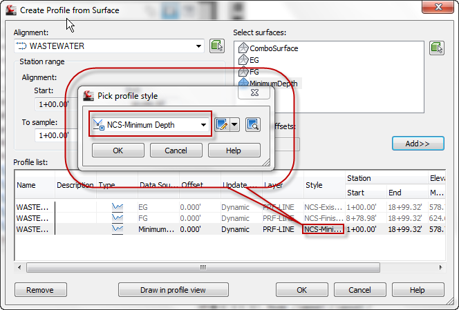
- In the Create Profile from Surface dialog box, select the alignment, select the MinimumDepth surface, then left click on Add.
- Change the style of the newly created profile to a style called "Minimum Depth". This style places the profile linework on a layer that doesn't plot and has a forced color and linestyle to look different from all other profiles.



Monday, September 12, 2011
Multiple Surface Dilemma (Part 2)
NOTE: This is Part 2 of the Multiple Surfaces Dilemma Series. You can view Part 1 of the series here. In Part 1 of this series, a surface named ComboSurface was created. Make sure
you create that surface in your drawing before proceeding with these
steps.
In this post, I'm going to assign the ComboSurface to the Pipe Network in the network properties dialog box.
Now as I place pipes and structures in this pipe network, the correct elevation will be used/reported (EG or FG) according to the location of the pipe or structure. Remember, you don't want this surface visible, just create it and select it from the list of surfaces when needed.
In this post, I'm going to assign the ComboSurface to the Pipe Network in the network properties dialog box.
- Since the pipe network has already been created in my drawing, I just need to locate it in the Prospector tab of Toolspace, select it, right click, and choose Network Properties.

- Set the surface name to ComboSurface.


Now as I place pipes and structures in this pipe network, the correct elevation will be used/reported (EG or FG) according to the location of the pipe or structure. Remember, you don't want this surface visible, just create it and select it from the list of surfaces when needed.
Friday, May 27, 2011
Out With the Old, In With the New
While reading discussions on the LinkedIn AutoCAD Civil 3D Users Group, I began typing this response that I later decided was worth sharing with others.
The discussion was on why firms are still using LDD instead of Civil 3D. The responses are typically:
Learning Civil 3D takes either enthusiasm to learn and embrace new software or a mandate from management to learn it. My current firm mandated the change and now my coworkers actually request making the change from LDD to Civil 3D on projects whenever possible. In fact, just last week I helped a coworker use Civil 3D to do something with surfaces that he was unable to do in LDD. Using LandXML and drawing objects, the procedure was done very efficiently in Civil 3D yet the final product is still in the original LDD project file format.
For Civil 3D, there are so many training aids available (many of them free, especially if you are on subscription) including a Home Use License, Autodesk University recorded videos and handouts, subscription training videos, YouTube, etc.
For me to learn Civil 3D, after a couple of employer paid training classes, I requested a Civil 3D Home Use License from the company's Autodesk contract administrator and spent hours learning to create a project from scratch with Civil 3D. Of course the time I spent at home was not paid, but it gave me an opportunity to learn the software better than anyone else at the company. Now with Civil 3D experience being a more valuable commodity in the workplace, the time I spent unpaid was well worth it. Also, the fact that I learned it before more and more features were added helped a lot too. Instead of learning EVERYTHING at once, I learned alignments, then profiles. Next I tackled surfaces, then pipes, etc. I suggest you do the same thing to learn the software. Don't try to swallow the whole bottle at once, it can be overwhelming. Take smaller bites and see how they taste.
Workflows for Civil 3D are so different than LDD. Until you can put that mentality aside, you will struggle to learn the software. As for the software not doing what you want from a surveying or civil engineering perspective, join the Autodesk beta testing community or post your feature request to the Civil 3D wish list on the AUGI forums. Not using the software because a feature doesn't exist won't get that feature there any faster. Besides, the feature may be there just in a different format than where you expect. This is where local Civil 3D User Groups or discussion forums can be a great asset.
As a great man I know once said, "Don't give me problems, give me solutions!" I think we should all take this approach more, so here's my possible solution for you:
First get a copy of the software to begin your training. Download Civil 3D from the Autodesk website and begin your 30 day product trial or request a Home Use License from your contract administrator if you are on subscription. Of course you'll need a computer that can run Civil 3D. If that isn't a possibility, set aside a few hours a week to stay late, arrive early, or train through your lunch hour on your work computer.
Start with an existing project. Begin creating that project from scratch. This way you're not facing deadlines or trying to learn the software and design at the same time. Get the whole team together and work through issues of how to complete a particular task. Watch some training videos at home after you put the kids to bed. Take notes then duplicate the procedures at lunch the next day.
Another thing that will help with implementation of Civil 3D is to create templates for your firm. Yes, there's an NCS standard template that's provided with Civil 3D out of the box, but let's face it, there's not a single box of chocolates that pleases everyone and templates are no different.
Create a CAD standard and setup your templates to implement those CAD standards. If you get rid of some of the up front work, you'll be surprised how much easier it is for users to become efficient with the software and comply with CAD standards at the same time.
Here's an example: Our firm has a template setup just for existing utilities. It already contains pipe networks for each existing utility with all defaults set. You can be up and running and creating pipes and structures with this file in minutes. You don't have to go through the trouble of setting up the pipe network parts list, the pipe network itself, the default layer names, default pipe and structure names, default pipe and structure styles and labels, etc. It's incredible how much time this will save you and how much you don't have to know about using the software because it's already done for you.
Here are a few more suggestions for learning to use Civil 3D:
I think many firms overlook the value of using the current software as a tool instead of as a crutch. Don't be one of those firms!
The discussion was on why firms are still using LDD instead of Civil 3D. The responses are typically:
- cost of training
- no time to learn it
- "if it ain't broke, don't fix it" attitudes
- lack of initiative to make it happen
Learning Civil 3D takes either enthusiasm to learn and embrace new software or a mandate from management to learn it. My current firm mandated the change and now my coworkers actually request making the change from LDD to Civil 3D on projects whenever possible. In fact, just last week I helped a coworker use Civil 3D to do something with surfaces that he was unable to do in LDD. Using LandXML and drawing objects, the procedure was done very efficiently in Civil 3D yet the final product is still in the original LDD project file format.
For Civil 3D, there are so many training aids available (many of them free, especially if you are on subscription) including a Home Use License, Autodesk University recorded videos and handouts, subscription training videos, YouTube, etc.
For me to learn Civil 3D, after a couple of employer paid training classes, I requested a Civil 3D Home Use License from the company's Autodesk contract administrator and spent hours learning to create a project from scratch with Civil 3D. Of course the time I spent at home was not paid, but it gave me an opportunity to learn the software better than anyone else at the company. Now with Civil 3D experience being a more valuable commodity in the workplace, the time I spent unpaid was well worth it. Also, the fact that I learned it before more and more features were added helped a lot too. Instead of learning EVERYTHING at once, I learned alignments, then profiles. Next I tackled surfaces, then pipes, etc. I suggest you do the same thing to learn the software. Don't try to swallow the whole bottle at once, it can be overwhelming. Take smaller bites and see how they taste.
Workflows for Civil 3D are so different than LDD. Until you can put that mentality aside, you will struggle to learn the software. As for the software not doing what you want from a surveying or civil engineering perspective, join the Autodesk beta testing community or post your feature request to the Civil 3D wish list on the AUGI forums. Not using the software because a feature doesn't exist won't get that feature there any faster. Besides, the feature may be there just in a different format than where you expect. This is where local Civil 3D User Groups or discussion forums can be a great asset.
As a great man I know once said, "Don't give me problems, give me solutions!" I think we should all take this approach more, so here's my possible solution for you:
First get a copy of the software to begin your training. Download Civil 3D from the Autodesk website and begin your 30 day product trial or request a Home Use License from your contract administrator if you are on subscription. Of course you'll need a computer that can run Civil 3D. If that isn't a possibility, set aside a few hours a week to stay late, arrive early, or train through your lunch hour on your work computer.
Start with an existing project. Begin creating that project from scratch. This way you're not facing deadlines or trying to learn the software and design at the same time. Get the whole team together and work through issues of how to complete a particular task. Watch some training videos at home after you put the kids to bed. Take notes then duplicate the procedures at lunch the next day.
Another thing that will help with implementation of Civil 3D is to create templates for your firm. Yes, there's an NCS standard template that's provided with Civil 3D out of the box, but let's face it, there's not a single box of chocolates that pleases everyone and templates are no different.
Create a CAD standard and setup your templates to implement those CAD standards. If you get rid of some of the up front work, you'll be surprised how much easier it is for users to become efficient with the software and comply with CAD standards at the same time.
Here's an example: Our firm has a template setup just for existing utilities. It already contains pipe networks for each existing utility with all defaults set. You can be up and running and creating pipes and structures with this file in minutes. You don't have to go through the trouble of setting up the pipe network parts list, the pipe network itself, the default layer names, default pipe and structure names, default pipe and structure styles and labels, etc. It's incredible how much time this will save you and how much you don't have to know about using the software because it's already done for you.
Here are a few more suggestions for learning to use Civil 3D:
- First of all USE THE SOFTWARE! If management provides training and you don't use the software, then you're probably going to struggle to remember what you learned.
- If you don't have time to create templates yourself, then pay someone to do it for you.
- Set deadlines then enforce them. Request a progress set on the pilot project as if it were a real project.
- Work with your employees to get the most from them. Offer an incentive to completing their first project using Civil 3D.
I think many firms overlook the value of using the current software as a tool instead of as a crutch. Don't be one of those firms!
Thursday, May 5, 2011
Water Structures in Profile View
You know that special symbol for water valves and fire hydrants that the engineers want to see in profile views of water lines? Ours looks something like this:
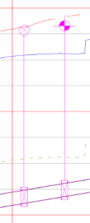
If you think it's a structure style, then you're wrong. It's actually a label style that uses several custom expressions. I use a block that is a rectangle on a no plot layer for the structure in profile view. You can leave the no plot structure visible, or you can turn off the display of the structure in profile view once you've added your labels.
This label will move with the structure, adjust to the size of the structure, and adjust to changes in the surface referenced in the structure. Adjusting the custom expressions, you can control how far all four sides of the rectangle are from the center of the structure based on the size of the structure.
Now if only we could assign a default label style to each structure in profile view I could finish my P&P sheets even quicker. For now, I'm just happy that I don't have to place a dynamic block at each structure then remember to go back and move it as my structure moves to an updated location.

If you think it's a structure style, then you're wrong. It's actually a label style that uses several custom expressions. I use a block that is a rectangle on a no plot layer for the structure in profile view. You can leave the no plot structure visible, or you can turn off the display of the structure in profile view once you've added your labels.
This label will move with the structure, adjust to the size of the structure, and adjust to changes in the surface referenced in the structure. Adjusting the custom expressions, you can control how far all four sides of the rectangle are from the center of the structure based on the size of the structure.
Now if only we could assign a default label style to each structure in profile view I could finish my P&P sheets even quicker. For now, I'm just happy that I don't have to place a dynamic block at each structure then remember to go back and move it as my structure moves to an updated location.
Thursday, March 31, 2011
Multiple Surface Dilemma (Part 1)
Have you ever needed to create a pipe network that involves two different surfaces? Well, I'm going to show you a workflow that could make this situation a breeze.
In this example, I'm working with an alignment that crosses both an existing ground surface (EG) and a finished ground surface (FG). I've already created the alignment and I've added both surfaces via data reference. Here's how it looks so far:
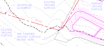
Now, the pipes in this drawing will need to stay a minimum distance below the existing ground surface (EG) until the alignment crosses into the finished ground surface (FG). At that point the pipes will need to stay a minimum distance below the finished ground surface. So how can I do that? I'm going to make a surface that is a combination of those two surfaces.
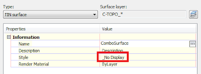
The first thing I'm going to do is create a surface called ComboSurface. In this case, I don't need to see the final product of the combined surfaces, so I'm going to set the surface style to _No Display.
Now I need to add some substance to this surface. I'll do that by pasting the existing ground surface (EG) and finished ground surface (FG) into the new ComboSurface.
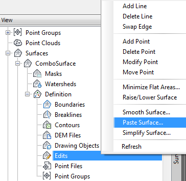
It's okay to select both surfaces at once.
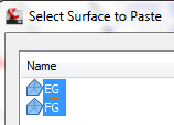
When pasting surfaces into another surface, ORDER IS EVERYTHING! That means I need to make sure that the order is correct. Open the Surface Properties for the ComboSurface and select the Definition tab.
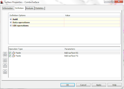 As you can see, the EG surface is at the top of the list and the FG surface is second in the list. This is exactly what I want for this surface. If the order is incorrect, select the EG surface and then left click on the "take me to the top up arrow"
  to send the EG surface to the top of the list.
Next, I need to make sure that this surface is set to Rebuild Automatically. To do this, I select the surface in toolspace, right click, then look for a check mark by Rebuild - Automatic. If there is no check mark ( ), I left click on Rebuild - Automatic to enable this feature. If the check mark is there (
 ), I press ESC to cancel the change.
Now I have a surface that can be used for all the pipes and structures in my network!
In Part 2 of this series, I'll show you how to use this new surface in your pipe network.
In this example, I'm working with an alignment that crosses both an existing ground surface (EG) and a finished ground surface (FG). I've already created the alignment and I've added both surfaces via data reference. Here's how it looks so far:

Now, the pipes in this drawing will need to stay a minimum distance below the existing ground surface (EG) until the alignment crosses into the finished ground surface (FG). At that point the pipes will need to stay a minimum distance below the finished ground surface. So how can I do that? I'm going to make a surface that is a combination of those two surfaces.
The first thing I'm going to do is create a surface called ComboSurface. In this case, I don't need to see the final product of the combined surfaces, so I'm going to set the surface style to _No Display.

Now I need to add some substance to this surface. I'll do that by pasting the existing ground surface (EG) and finished ground surface (FG) into the new ComboSurface.

It's okay to select both surfaces at once.

When pasting surfaces into another surface, ORDER IS EVERYTHING! That means I need to make sure that the order is correct. Open the Surface Properties for the ComboSurface and select the Definition tab.
 As you can see, the EG surface is at the top of the list and the FG surface is second in the list. This is exactly what I want for this surface. If the order is incorrect, select the EG surface and then left click on the "take me to the top up arrow"
  to send the EG surface to the top of the list.
Next, I need to make sure that this surface is set to Rebuild Automatically. To do this, I select the surface in toolspace, right click, then look for a check mark by Rebuild - Automatic. If there is no check mark (
 ), I left click on Rebuild - Automatic to enable this feature. If the check mark is there (
 ), I press ESC to cancel the change.
Now I have a surface that can be used for all the pipes and structures in my network!
In Part 2 of this series, I'll show you how to use this new surface in your pipe network.
Tuesday, December 30, 2008
Removing A Civil 3D Object Without Using the AutoCAD Erase Command
Sometimes using AutoCAD commands on Civil 3D objects is okay and sometimes it causes problems. For example: deleting parcel segments or pipe network objects. According to Autodesk, deleting a pipe using the AutoCAD erase command has been corrected in Civil 3D 2009, but since I know some of you may still be using Civil 3D 2008 or earlier, I'm going to show you the proper way to delete an object in Civil 3D.
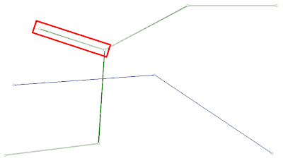
Here I have two pipe networks Water (blue) and Wastewater (green). After a round of revisions, the pipe and one of the structures in the red rectangle needs to be removed.
 I know it's very tempting to just run the erase command and select the structure and pipe to be deleted, but that's what causes the issue. Here's the proper way to delete the structure and pipe.
From the Pipes menu list, select "Edit Pipe Network...".
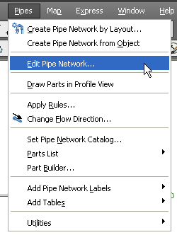 The command line prompts you to "Select part from pipe network:". After you select the pipe or structure you are deleting, the Network Layout Tools toolbar will appear. The tool you want is the "Delete Pipe Network Object".
 After selecting the "Delete Pipe Network Object" tool, you are prompted to "Select Structure or Pipe". Left click on any structures or pipes that you want deleted from the network.
The reason you should always delete pipe network objects using this tool is because the pipe network part must be disconnected from other parts in the network before they are removed from the drawing.
Something similar happens with parcels so be sure to delete parcel segments using the appropriate tool as well.
[Parcels - Edit Parcel - Edit Parcel Segments]
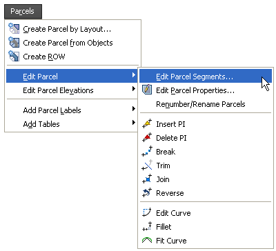 The tool is labeled "Delete Sub-entity".

Here I have two pipe networks Water (blue) and Wastewater (green). After a round of revisions, the pipe and one of the structures in the red rectangle needs to be removed.
 I know it's very tempting to just run the erase command and select the structure and pipe to be deleted, but that's what causes the issue. Here's the proper way to delete the structure and pipe.
From the Pipes menu list, select "Edit Pipe Network...".
 The command line prompts you to "Select part from pipe network:". After you select the pipe or structure you are deleting, the Network Layout Tools toolbar will appear. The tool you want is the "Delete Pipe Network Object".
 After selecting the "Delete Pipe Network Object" tool, you are prompted to "Select Structure or Pipe". Left click on any structures or pipes that you want deleted from the network.
The reason you should always delete pipe network objects using this tool is because the pipe network part must be disconnected from other parts in the network before they are removed from the drawing.
Something similar happens with parcels so be sure to delete parcel segments using the appropriate tool as well.
[Parcels - Edit Parcel - Edit Parcel Segments]
 The tool is labeled "Delete Sub-entity".
Thursday, April 10, 2008
PVLS PART 4: Offsetting a Profile View Label
This is Part 4 of a series on Profile View Label Styles (PVLS). This post may not make a whole lot of sense if you haven't seen the previous posts in this series. Please take a moment to read them before continuing to read this one. Here's a link to each:
PVLS PART 1: Creating Profiles for Labeling Crossing or Connecting Pipe Flowline Elevations
PVLS PART 2: Creating the Style for the Connecting Pipe Flowline Elevation Label
PVLS PART 3: Labeling the Crossing or Connecting Pipe Flowline Elevations
To use the Offset Style created in this series, you'll need to create the label style first. (Instructions for creating an offset label style can be found Part 2 of this series.
After the style has been created, right click on the style and select New... in the Settings tab of the Toolspace. For Profile Views, this will create a "Child" of the original style. It will have all the same properties and components of the original style at the time that it is created except those that you change.
On the Information tab, rename the text inside the brackets [child] to [RT-0.3]. That means that we will be creating a style that moves the text right 0.3 inches. Go ahead and left click on Apply then select the Layout tab.
Remember how we deleted the original text so that the first component was "Line for Text". This is where it comes into play.
Go to the Line section and change the Start Point X Offset to 0.3, then Apply and OK. Now place the style in the drawing or change one of the existing labels to use this style instead. Here's a screen capture of the original parent style and the new offset RT child style.

There are other ways to change the style as well. Try changing these values and see how they affect the style:
Well, that's it for my series on Profile View Label Styles. I hope you found it useful. Feel free to post a comment if you have questions or if you just want to request a topic for a future post.
Technorati Tags: Civil 3D Pipes Profile View Styles Tutorial
PVLS PART 1: Creating Profiles for Labeling Crossing or Connecting Pipe Flowline Elevations
PVLS PART 2: Creating the Style for the Connecting Pipe Flowline Elevation Label
PVLS PART 3: Labeling the Crossing or Connecting Pipe Flowline Elevations
To use the Offset Style created in this series, you'll need to create the label style first. (Instructions for creating an offset label style can be found Part 2 of this series.
After the style has been created, right click on the style and select New... in the Settings tab of the Toolspace. For Profile Views, this will create a "Child" of the original style. It will have all the same properties and components of the original style at the time that it is created except those that you change.
On the Information tab, rename the text inside the brackets [child] to [RT-0.3]. That means that we will be creating a style that moves the text right 0.3 inches. Go ahead and left click on Apply then select the Layout tab.
Remember how we deleted the original text so that the first component was "Line for Text". This is where it comes into play.
Go to the Line section and change the Start Point X Offset to 0.3, then Apply and OK. Now place the style in the drawing or change one of the existing labels to use this style instead. Here's a screen capture of the original parent style and the new offset RT child style.

There are other ways to change the style as well. Try changing these values and see how they affect the style:
- The length of the "Line at Insertion Point"
- The length of the "Line for Text"
- The Start Point Y Offset of the "Line for Text"
Well, that's it for my series on Profile View Label Styles. I hope you found it useful. Feel free to post a comment if you have questions or if you just want to request a topic for a future post.
Technorati Tags: Civil 3D Pipes Profile View Styles Tutorial
PVLS PART 3: Labeling the Crossing or Connecting Pipe Flowline Elevations
This is Part 3 of a series on Profile View Label Styles (PVLS). You should also read Part 1 and Part 2 of this series for additional information.
To label a crossing and/or connecting pipe flowline elevation, you'll need the style created in Part 2 of this series and profiles for both the main line and the crossing/connecting pipes as described in Part 1 of this series.
After you have the style and profiles created in your drawing, the rest is really simple.
Well, that's it for Part 3. In Part 4, I will describe how to use the offset capability that we put in place when we created the Profile View Station Elevation Label Style in Part 2 of this series.
Technorati Tags: Civil 3D Pipes Profile View Styles Tutorial
To label a crossing and/or connecting pipe flowline elevation, you'll need the style created in Part 2 of this series and profiles for both the main line and the crossing/connecting pipes as described in Part 1 of this series.
After you have the style and profiles created in your drawing, the rest is really simple.
- Zoom into the connecting pipe that you want to label.
- From the Civil 3d Profile menu, select "Add Profile View Labels", then "Add Profile View Labels...".
- In the Add Labels dialog box, select the style that you created from Part 2 of this series (mine was called Connecting Pipe Label).
- Choose a Marker style if you want one. I don't generally use one for this style.
- Left click on the Add command button.
- You will be prompted to select a profile view. Select the profile view by left clicking on one of the grid lines, not the actual profile.
- When asked to specify a station, select the endpoint at the flowline of the crossing pipe shown in the profile view.
- When asked to specify an elevation, you can either select the same point or specify an elevation for the insertion point of the label.
- Repeat this process for other connecting pipe labels that are visible in this profile view.
- If you need to add labels in other profile views, you'll need to left click on the Add command button again to select a different profile view.
- Select all the connecting pipe labels in one profile view and then look at the properties listed on the labels. There is a Civil 3D section that contains a listing for Profile1 Object and Profile2 Object. They will be set to
by default. - Left click on the
for Profile1 Object and set that to the profile you created for the flowline of the main pipe. - Left click on the
for Profile2 Object and set that to the profile you created for the crossing and/or connecting pipes and pipe size changes.
Well, that's it for Part 3. In Part 4, I will describe how to use the offset capability that we put in place when we created the Profile View Station Elevation Label Style in Part 2 of this series.
Technorati Tags: Civil 3D Pipes Profile View Styles Tutorial
PVLS PART 2: Creating the Style for the Connecting Pipe Flowline Elevation Label
This is Part 2 of a series on Profile View Label Styles (PVLS). You can view Part 1 of the series here.
Here's the step by step guide to creating the Station Elevation Profile View Label Style. The way this style is created will enable you to easily establish offsets in child styles as needed. That will be explained in a Part 4 of this series.
Technorati Tags: Civil 3D Pipes Profile View Styles Tutorial
Here's the step by step guide to creating the Station Elevation Profile View Label Style. The way this style is created will enable you to easily establish offsets in child styles as needed. That will be explained in a Part 4 of this series.
- If toolspace is not visible, type showts at the command line and press enter.
- Select the Settings tab.
- Double click "Profile View" in the list under your current drawing name.
- Double click "Label Styles".
- Right click "Station Elevation" and select "New...".
- On the Information tab, type a name for your style. I'll use Connecting Pipe Label for this example.
- On the General tab, set the layer as required. I'll use PROF-VIEW-TX for this example.
- On the Layout tab, delete the default "Station & ELevation" component (yes, the "L" is really capitalized) that is created by clicking on the
 near the top middle of the Label Style Composer dialog box. I do this because I want a different component to be the first one that appears when the Layout tab is selected in the future.
 - Select Line from the Create Component dropdown list.

- Under the General section:
- Change the Name property to Line for Text,
- Set the Start point anchor point to Middle Center.
- Under the Line section:
- Change the Length to 2.0000",
- Set the Angle to 270° 00' 00",
- Set the Start Point Y Offset to -0.5000". This moves the beginning of the line down 0.5 inches from the point you select for placing the label.
- At this point, you're probably looking at the preview side of the Label Style Composer dialog box to see how things are looking. Unfortunately, the default preview state for a Profile View Station Elevation Label is set to Depth Label Style. So click the drop down arrow near the upper right corner of the Label Style Composer dialog box and select "Station Elevation Label Style" to watch the style update as you apply the changes.

- At this point, go ahead and select Apply so that everything up to this point will be saved.
- Create another line component (same as step 9).
- Under the General section:
- Change the Name property to Line at Insertion Point,
- Set the Start point anchor point to Middle Center.
- Under the Line section:
- Change the Length to 0.2500",
- Set the Angle to 270° 00' 00".
- Now create one more line component (same as step 9). This may seem unusual, but it will make sense at the end of the post.
- Under the General section:
- Change the Name property to Offset Connection Line,
- Set the Start point anchor component to Line at Insertion Point,
- Set the Start point anchor point to End,
- Set the Use End Point Anchor to True,
- Set the End Point Anchor Component to Line for Text,
- Verify that the End Point Anchor Point is set to Start.
- Select Apply again to save the changes up to this point. The preview tab will show that the label currently appears as if there is just one solid line.
- Create a text component from the create component list.

- Under the General section:
- Change the Name property to Station and Flowline Text,
- Set the Start point anchor point to Line for Text,
- Set the Anchor Point to End.
- Under the Text section:
- Edit the Contents as follows:
- On the format tab, set the Justification to Left,
- Insert text appropriate for the style you are creating. For my example, I used this text:
STA <[Station Value(Uft|FS|P2|RN|AP|Sn|TP|B2|EN|W0|OF)]> SSL-XX=
STA 1+00 SSL-XX
FL (XX")=<[Profile1 Elevation(Uft|P2|RN|AP|Sn|OF)]>
FL (XX")=<[Profile2 Elevation(Uft|P2|RN|AP|Sn|OF)]>
I also force the XX values to a different color so that I know that these values have to be manually edited and updated as required. It ends up looking something like this:
- Set the Attachment point to Bottom Right (Don't ask me why. I think it should be set to Top Left, but once the text is perpendicular to the view, it seems that you have to set it to the opposite of what you think it should be.)
- Apply, OK, and your style is complete.


Technorati Tags: Civil 3D Pipes Profile View Styles Tutorial
PVLS PART 1: Creating Profiles for Labeling Crossing or Connecting Pipe Flowline Elevations
This is Part 1 of a series on Profile View Label Styles (PVLS). I will discuss how to label the flowlines of connecting pipes in a profile view. Armed with this information, you should be able to create your own style that shows flowlines of pipes at crossings and at changes in pipe sizes.
Well this is one label style with which I've been wrestling for some time. Then while creating an offset label style the other day, it just hit me how easy it would be to get the two flowline elevations into one style. Now, at this point, the pipe size in this particular style has to be edited manually, but maybe this style might give you some ideas on how to get everything you want labeled automatically.
The first thing you need to do is create a profile style with Line, Circular Curve, Symmetrical Parabola, and Asymmetrical Parabola component types visible, but on a "no-plot" layer. For my style, I've create a layer called _no-plot-profile and set the Plot property to "No".

Now create a profile by layout that follows the flowline of the main pipe in your profile view. Be sure to use the "no-plot-profile" style that you just created. This profile can also be used to label your pipe flowline elevations (such as the elevations shown in a band style).

Now create a second profile by layout that connects the flowline of all your crossing or connecting pipes. You can also tag the end of the smaller pipe at a pipe change (since a profile can't be exactly vertical). The second profile should look something like this:

Here's a zoomed in view of the three major locations where I use the "crossing pipe" profile. (Just click on the image to see an enlarged view.)

Well, that's it for Part 1. In Part 2, I will describe how to create the Profile View Station Elevation Label Style.
Technorati Tags: Civil 3D Pipes Profile View Styles Tutorial
Well this is one label style with which I've been wrestling for some time. Then while creating an offset label style the other day, it just hit me how easy it would be to get the two flowline elevations into one style. Now, at this point, the pipe size in this particular style has to be edited manually, but maybe this style might give you some ideas on how to get everything you want labeled automatically.
The first thing you need to do is create a profile style with Line, Circular Curve, Symmetrical Parabola, and Asymmetrical Parabola component types visible, but on a "no-plot" layer. For my style, I've create a layer called _no-plot-profile and set the Plot property to "No".

Now create a profile by layout that follows the flowline of the main pipe in your profile view. Be sure to use the "no-plot-profile" style that you just created. This profile can also be used to label your pipe flowline elevations (such as the elevations shown in a band style).

Now create a second profile by layout that connects the flowline of all your crossing or connecting pipes. You can also tag the end of the smaller pipe at a pipe change (since a profile can't be exactly vertical). The second profile should look something like this:

Here's a zoomed in view of the three major locations where I use the "crossing pipe" profile. (Just click on the image to see an enlarged view.)

Well, that's it for Part 1. In Part 2, I will describe how to create the Profile View Station Elevation Label Style.
Technorati Tags: Civil 3D Pipes Profile View Styles Tutorial
Saturday, January 12, 2008
Pipe Network Recovery
I'm sure some of you have experienced corrupt drawings containing pipe networks. It usually becomes apparent right after an audit when all the pipes from at least one pipe network just "disappear".
Unfortunately, the answer from Autodesk web support is usually that you'll have to go to a backup or rebuild the pipe networks from scratch. Well, I found something this week that might help the process of re-creating those pipe networks.
If you list one of the corrupt pipes, you'll notice that there is no "Pipe Network" reference in the "corrupt" pipe. The first image is a sample of a "good" pipe, the second image is a sample of a "corrupt" pipe.
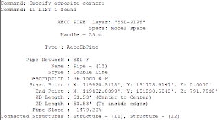

You could use the plan set (if you have one already) to recreate the pipe network, but if you don't have one, here's another way.:
Create a pipe style that shows only the Plan Pipe Centerline and the Plan Pipe End Line. Also create a pipe label style that shows the inside pipe diameter. The pipe ends will assist you in knowing where the pipes begin and end and the centerline will give you an elevation for the pipe. You should also label the structures so that you'll know which one to place.
Now you can create the pipe network by layout snapping to the endpoints of the pipe centerline for elevation and changing the pipe sizes as necessary based on the inside pipe diameter label.
Obviously, this isn't a cure-all and it will still take some time to complete, but hopefully it might help you get back up and running a little bit quicker.
Unfortunately, the answer from Autodesk web support is usually that you'll have to go to a backup or rebuild the pipe networks from scratch. Well, I found something this week that might help the process of re-creating those pipe networks.
If you list one of the corrupt pipes, you'll notice that there is no "Pipe Network" reference in the "corrupt" pipe. The first image is a sample of a "good" pipe, the second image is a sample of a "corrupt" pipe.


You could use the plan set (if you have one already) to recreate the pipe network, but if you don't have one, here's another way.:
Create a pipe style that shows only the Plan Pipe Centerline and the Plan Pipe End Line. Also create a pipe label style that shows the inside pipe diameter. The pipe ends will assist you in knowing where the pipes begin and end and the centerline will give you an elevation for the pipe. You should also label the structures so that you'll know which one to place.
Now you can create the pipe network by layout snapping to the endpoints of the pipe centerline for elevation and changing the pipe sizes as necessary based on the inside pipe diameter label.
Obviously, this isn't a cure-all and it will still take some time to complete, but hopefully it might help you get back up and running a little bit quicker.
Subscribe to:
Posts (Atom)