Showing posts with label Civil 3D. Show all posts

Wednesday, December 26, 2018

Update to Set Working Folder Dialog

Set Working Folder Uses File Open Style Dialog

A new feature of Civil 3D 2019 is an update to the Set Working Folder dialog. Previously it was strictly a browse and select folder dialog. As of Civil 3D 2019, the Set Working Folder dialog now resembles a File Open dialog.


This may seem like something small but for those of you that must drill multiple folders deep to select the Working Folder for a project, this new dialog is a nice improvement because now you can copy then paste a folder path from the Windows Explorer address bar into the Set Working Folder dialog address bar or Folder path.

Monday, December 3, 2018

Convert Survey Figures to Polylines

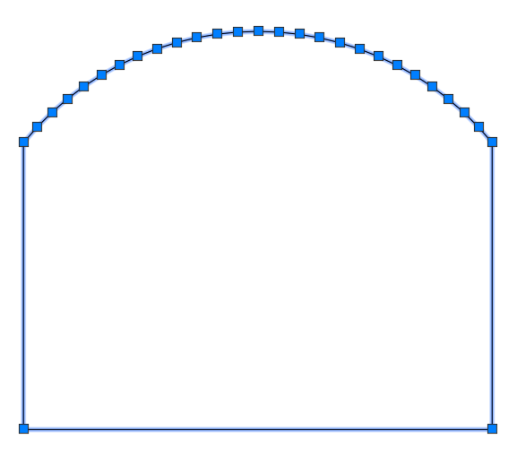
Sometimes survey figures are exactly what you want and other times you just want a polyline at elevation zero. If your like me, you created a figure style that flattens all elevations to zero then you exploded it. If that figure had an arcs, they became segmented like this:
I'm happy to report that there is a workflow to create these polylines with arcs from figures. I have confirmed that this workflow will work for versions 2016 through 2019. Note that the polylines will not update if the survey figure changes and is updated in the drawing.

Create a 2D figure style in your template

  1. In your template, expand the Toolspace > Settings tab > Survey > Figures category.
  2. Right click on Figure Styles and choose New.


  3. In the Figure Style dialog > Information tab, set the figure style name to 2D.


  4. In the Figure Style dialog > 3D Geometry tab, set the Figure display mode to Flatten figure to elevation and confirm that the Flatten figure to elevation is set to 0.00.


  5. In the Figure Style dialog > Display tab, change the layer, color, linetype, and so on to meet your CAD standards then click OK.
  6. Right click on the Toolspace > Settings tab > Survey category and choose Edit Feature Settings.


  7. In the Edit Feature Settings - Survey dialog, expand the Default Styles category and set the Default Figure Style to the 2D figure style you just created then click OK.


  8. Save and close the template.

Export Survey Figures to Polylines at Elevation Zero

  1. Begin a drawing with the template that contains the 2D figure style.
  2. Open a survey database and import figures to the drawing. The default style should be the 2D figure style.
  3. Set the UCS to World then save the drawing.
  4. In the application menu, select Export > Export Civil 3D Drawing.


      NOTE: Exploding figures using the 2D figure style will create polylines with segmented curves. That's why you'll need to use the Export Civil 3D Drawing command to get polylines with arcs.

  5. In the Export Autodesk Civil 3D Drawing dialog, choose the folder for the exported drawing then click Export.


  6. When the export is complete, click OK in the Export Status Dialog then Cancel in the Autodesk Civil 3D Drawing dialog.


  7. Open the exported drawing and confirm that the figures were exported to polylines at elevation zero.
  8. Select all the polylines representing exported figures and copy to the clipboard with a basepoint using SHIFT+CTRL+C and entering 0,0 as the base point.
  9. If you are replacing the figures in the original drawing, you can now delete them.
  10. In the original drawing, confirm that the UCS is set to World then use CTRL+V and enter 0,0 as the insertion point to paste the polylines into the correct location.
  11. Save the drawing.
An alternate workflow might be to have a separate template for importing just figures into a temp drawing so that you can export them and they will be on the correct layer. For this you'll need separate figure styles for each type of figure/layer combination you need. Then you can choose to import figures into the original base drawing onto the feature line or equivalent layer and have them displayed as a 3d object instead of a 2D object.

Monday, November 19, 2018

Set Your Site...On Feature Lines

When importing LandXML files into Civil 3D 2019, there's a new setting for Feature Lines:

Use this setting to select a site for the Feature Lines you are importing. You can select a site from the dropdown list or use the green pic icon to select a site in the drawing.

You can also assign a site independently for Alignments and Parcels if any exist in the LandXML file that is being imported.

Monday, March 28, 2016

Point to Point Inverse in Civil 3D

I find that map commands in Civil 3D can be very useful for both land surveyors and civil engineering technical staff. The problem seems to be that many users don't know about these very useful commands.

Here's a question than I'm often asked by land surveyors:
Is there a point to point inverse in Civil 3D?

The answer to this question is YES!
CGSLIST + the 'PN transparent command.

CGSLIST

CGSLIST is located on the Analyze ribbon tab in the Inquiry panel.


BEFORE YOU BEGIN

The help information for this command doesn't mention vertical difference, but that information is included in the output for this command.


This command uses the settings for Angle, Distance, and Direction that are stored in the Ambient Settings of the current drawing. If you want the course (bearing) to be in N90°00'00"E format, open the Drawing Settings dialog, choose the Ambient Settings tab, change the Direction > Format setting to DD°MM'SS" and press OK. You can also change the precision for coordinates, distances, and more.


You should also expand the command line so that you can see at least five lines of the command line history.


My example begins with a drawing that contains two points that are exactly 10 feet apart horizontally and 5 feet apart vertically. This allows me to confirm the horizontal and vertical results of the command.

Using the CGSLIST Command

  1. After selecting the Analyze ribbon tab, locate the Inquiry panel and click on the List Slope (CGSLIST) icon.


  2. When prompted, type P and press enter to use the Points selection option. Selecting the Points option here only notifies the command that you want to select coordinate points, not Civil 3D cogo points, for the input data type. 
  3.  

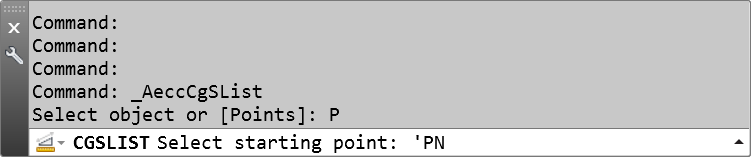
    NOTE: The command line shows that _AeccCgSList is the command running. You can also access this command by typing CGSLIST at the command line and pressing enter. If you are using Map 3D, use MAPCGSLIST. All three commands work in Civil 3D version 2015 or later. 

  4. When prompted to select a starting point, type 'PN and press enter. This will tell the command that you will be entering Civil 3D cogo point numbers instead of selecting coordinate points by clicking on the screen.


  5. When prompted to enter a point number, enter the starting cogo point number then press enter.


  6. The coordinates of the cogo point will appear in the command line history. Now enter the next cogo point number for the ending point then press enter.


  7. This command reports horizontal distance and elevation difference. It also reports the point elevations along with the grade and slope between the points. Notice that the distance shown is a horizontal distance, not a slope distance which is the result reported when using the DISTANCE or MEASUREGEOM command.

Now...
Don't be fooled!

Even though the command shows that the 'PN transparent command is still running, the CGSLIST command has reverted to the original Select object or [Points] prompt. At this point you'll need to press ESC to exit the 'PN transparent command, type P then enter to return to the Points selection, and finally type 'PN and press enter to return to the 'PN transparent command.

If you want a command that repeats with the 'PN transparent command, record a macro. If you're interested in a follow-up blog describing how to create and use that macro, please let me know in the comments section of this posting.

Wednesday, February 18, 2015

Where Do You Think You're Going?

I saw an interesting issue today with a General Line Label. Here's how it looked in the source drawing. A user imported a general line label style and added the label to an existing AutoCAD object in the new drawing. The problem was that the arrowheads were pointing in the wrong direction. It looked similar to this label.

A General Line Label with arrowheads at each end of the segment with the incorrect rotation angle.

I compared the style settings between the source and destination drawing. Everything matched exactly. The only difference between the original label and the new label is that the original label was on a polyline and the new label was on a line that had an elevation of 500 for one endpoint and an elevation of 0 for the other endpoint. Once I set one endpoint elevation to match the other endpoint (both at elevation 0), the label then looked exactly as it was designed to look.

A General Line Label with arrowheads at each end of the segment with the correct rotation angle.

Lesson of the day #1: Sometimes polylines are a better choice than a line for labeling.

Lesson of the day #2: OSNAPZ to the Rescue.

Monday, December 8, 2014

Resize Me!

Sometimes you learn things that you don't realize others haven't seen yet. During the CV6726-P - Attack of the Roundabouts: Conquer Them with Vehicle Tracking class taught by Brian Levendowski, Infrastructure Industry Manager, CAD Technology Center, Inc., I found this to be the case with resizing of viewports in the Model tab. When Brian did this during his presentation, the previously silent classroom was filled with Oohs and Aahs and the sound of pencils/pens and paper immediately followed. Since so many in that class had not seen this feature I decided to share it with you.

Here is the step by step description.
  1. Open any drawing with version AutoCAD 2015 or later, then set the View ribbon tab current. This also works in verticals such as Civil 3D.
    Select the View Ribbon Tab
  2. Locate the Model Viewports panel and left click on the words Viewport Configuration to activate the drop down selection list.
    Accessing the Viewport Configuration drop down selection list.
  3. From the drop down selection list, left click on Two: Vertical (or any other option except Single) to view multiple viewports on the Model tab of your current drawing.
    Select a viewport configuration with multiple viewports.
  4. With the multiple viewports visible, you can now hover your cursor over any of the adjoining lines between viewports, left click, hold, and drag to the desired location. When you get the line moved to the desired location, release the left mouse button.
Here's a video that shows these steps in action.


You can also add viewports by using the + as the beginning point of the left click, hold, and drag location. By dragging an existing viewport near another viewport boundary you can delete an existing viewport. To see this in greater detail, I refer you to Greg Battin's AutoCAD Tips blog post titled AutoCAD 2015 Resize Model Space Viewports.

Friday, January 18, 2013

Autodesk University 2012 Classes Posted

The materials and recordings for the 2012 Autodesk University classes have been posted. You can access the class list here:

You must have an AU account to access the classes. If you don't have an AU account, you can sign up for one here.

Since the announcement about this just went public, you may notice the website being a bit slow to respond. Just be patient because there are so many good classes available. In case you feel overwhelmed when you see the class listing, just refine your search such as Software: Civil 3D. There's even a filter for Language: Portuguese.

Enjoy!

OSNAPZ to the Rescue

Do you remember the Almond Joy/Mounds commercials?

(Sometimes you feel like a nut, sometimes you don't.)

The OSNAPZ command in AutoCAD reminds me of those commercials.

(Sometimes I want elevation, sometimes I don't.)

The OSNAPZ command is an easy way to switch between snapping to an elevation and forcing an elevation when creating or editing AutoCAD objects. When drafting in both the Civil Engineering and Land Surveying fields, both options are useful.

From the AutoCAD help documentation:

With OSNAPZ set to 0, OSNAP uses the Z-value of the specified point. For a polyline, the elevation selected for the first vertex will be assigned as the elevation of the polyline.

With OSNAPZ set to 1, OSNAP substitutes the Z-value of the specified point with the elevation (ELEV) set for the current UCS. With the system variable ELEV set to 0, the elevation will default to 0 for all selected points.

Now hopefully I can finally get that song out of my head.

Thursday, December 20, 2012

Which Way is North?

 Okay I admit it, the allure of one day being invited into the "Autodesk Expert Elite Program" has me checking the Autodesk Civil 3D Discussion Forums and blogging again. Since I'm only at the designated level of "Active Contributor", I have some work to do. Thanks, Autodesk!

The idea behind this post came from a question on the Autodesk Civil 3D Discussion Forums here. The issue is with a Civil 3D 2013 Dynamic North Arrow that is associated with a viewport with the UCS set to World, the dview twist angle set to "0", and the viewport set to plan. For some reason the north arrow was off by over 4.6 degrees. Bruce, a designated Autodesk "Expert Elite" himself, was kind enough to post a sample drawing to show the issue and here's what was discovered.:

Dynamic north arrows are associated with the 
selected coordinate system in the Units and Zone tab.

When you place a dynamic north arrow in a layout and associate it with a viewport, the block reads the current coordinate system that is assigned in the drawing settings Units and Zone tab and adjusts the default rotation of the block based on that setting. Even if there isn't a rotation in the viewport, the north arrow won't be pointing due north as you might expect. Here's an example.:

  1. In Civil 3D 2013, open an existing drawing or create a new drawing from scratch.
  2. On the model tab (modelspace) draw a rectangle of any size.
  3. In the Settings tab of Toolspace, right click on the drawing name and choose Edit Drawing Settings.
  4. On the Units and Zone tab, set the Drawing Settings Zone Categories to No Datum, No Projection.

    No Datum, No Projection

  5. In a layout (paperspace), create a rectangular viewport from scratch. Make sure you can see the rectangle in the viewport to verify rotation throughout this example. You may need to zoom out if necessary to see the rectangle rotation better.
  6. When you are in paperspace, there should be a Layout Tools ribbon tab available. Locate the Layout Elements Panel and select one of the built-in dynamic north arrows to place in the drawing.

    Select one of the built-in Dynamic North Arrows

  7. When prompted at the command line, select a viewport for the north arrow association.
  8. Next you'll be prompted to select a location to place the north arrow.
  9. The north arrow may be very small and hard to see. Set the x, y, and z scales to 20. Notice that it appears to be pointing due north when compare to the rectangle in the viewport.

    North is North
  10. To make sure we compare apples to apples, make a copy of the viewport in your drawing.
  11. Back in the Toolspace, Settings, Drawing Settings, Units and Zone tab, set the selected coordinate system to WA83-SF, then OK.
  12. Now place a new dynamic north arrow in the drawing using the second viewport (the copy) for the north arrow association. (Only one dynamic north arrow can be assigned to each viewport.)
  13. Place the second north arrow near the first one and again set the x, y, and z scales to 20.
  14. Notice that the north arrows don't point the same direction? That's because of the change made to the selected coordinate system.

    Compare the Dynamic North Arrows
This is definitely something that you need to take into consideration when you use the dynamic north arrows in a drawing with an assigned coordinate system other than No Datum, No Projection. If you do need to rotate the contents of a viewport, just set the coordinate system back to No Datum, No Projection before making the change, then reset the coordinate system as needed.

Another consideration is to set the coordinate system in the base drawing and attach it to a separate sheet drawing for plotting. The sheet doesn't need a coordinate system assigned to it so there won't be a discrepancy between plan north and the rotation of the dynamic north arrow.

UPDATE:  There is another solution that actually works better.

GEOGRAPHICLOCATION

In modelspace, type GEO at the command line then choose Remove the geographic location.


With the geographic location removed, you can keep the coordinate system assigned and the dynamic north arrow will point plan north as expected.

Tuesday, December 11, 2012

Slow Down and Render This

Yesterday, I received an email with an attached drawing. Verbally, the request was to determine why the drawing is so slow, especially when using the zoom extents.The email included the following additional information:

This file was messing up badly on Wednesday...crazy slow, etc.

This morning with my new reload of AutoCAD 2011, it wasn't as bad... but still has signs of corruption...


One thing that I noticed is that the TIN in the V-TINN-VIEW layer doesn't look right... the contours are fine... but I didn't know if you had a fix for that...


There are lots of things that can cause a drawing to be a little slow. I have a list of things I check in a drawing but I knew that many of those had already been checked by the owner of this drawing. The comment about the TIN not looking correct was definitely a clue to the problem as was the knowledge that the user had recently been working with point clouds including some third party software.

I knew the fresh install and absence of the third party software had ruled out that being the issue so my first option was simply to open the drawing. Here's what I saw in the bottom left corner of the application:

This is not the ucs icon that I typically see in my drawings. The thickness of the ucs icon elements was an indication to me that the visual style was set to something other than 2D Wireframe.

To verify my suspicion, on the View ribbon tab, I selected the dropdown on the Views Panel and found the visual style was set to Hidden.


 I left clicked on the Hidden visual style and changed the visual style to 2D Wireframe.


Now the ucs icon looks as expected and the speed of the drawing has returned to "normal".


Now if you are using AutoCAD 2012 or later, take a look at the upper left corner of model space. There you should find the Visual Style Controls.


As you can see, the visual style in this drawing is now set to 2D Wireframe. Changing this setting from Hidden to 2D Wireframe greatly improved the speed of the drawing.

Tuesday, December 13, 2011

Quick Tip about Importing Styles and Settings


If you're using Civil 3D 2012, you've hopefully already heard about the ability to Import Styles and Settings. This new command is a real time saver but be careful, because you may not be getting everything you want.

Here are a few things you won't get by using the Import Styles Command:

  • Object Layer Settings (Use this workaround to transfer the settings to your current drawing)
  • Blocks and Layers not used in styles (Use Design Center to import all layers and blocks)
  • Description Key (Use old style drag & drop to import into your current drawing)
  • Parts Lists (Use old style drag & drop to import into your current drawing)
There may be more items that aren't imported, but those three items will definitely be missing if you use the Import Styles command.

Feel free to add comments for additional items that you find missing when you use the command.

Added Parts Lists per TimStalin's comment.

Friday, November 11, 2011

What's Missing In the World of Civil 3D Points? Not This!


Sure there are feature requests that we all have for Civil 3D points such as having full functionality of dynamic blocks within a point style, but this post is actually about what is no longer missing.


This morning I was asked how to find ranges of point numbers that were not currently being used in a drawing. In older versions of Civil 3D, one might have tried to look at the All Points point group properties for a list of points in that group. Well, now there's an easier way to get the answer.

Beginning with Civil 3D 2011, we were given this nifty new command:

LISTAVAILABLEPOINTNUMBERS

This command returns a list of point numbers that are not in use in the current drawing. Now you might be thinking that is a really long command name to remember but don't panic. Here's a how you can access the command:
  1. In Civil 3D 2011, at the command line, type LISTA then press tab then enter. Civil 3D will auto-complete the command for you.
  2. In Civil 3D 2012, at the command line, type LISTA then press enter (no tab key required). Civil 3D will auto-complete the command for you.
  3. In Civil 3D 2011 or 2012, select a Civil 3D point. On the COGO Point contextual ribbon tab, look for the COGO Point Tools panel . Left click on the bottom of that panel and a fly out will appear. Choose List Available Point Numbers from the list.


So now you know one thing that is no longer missing from the world of Civil 3D points.

Wednesday, September 21, 2011

Multiple Offsets are Already Here

Have you ever wanted to offset a line multiple times within one command? See how after the jump...


Thursday, September 15, 2011

Properties vs List - Same or Different?

Though the properties palette is packed with information, there may be something missing. Here's an example of information that the list command reports that isn't available in the properties palette:

In Figure 1.0, there are four feature lines. The three red feature lines have been added to the surface, but the fourth feature line (the blue one) has not been added to the surface. How do I know that? It's all in the properties...just not the properties palette.
Figure 1.0
Figure 1.1 shows the information that is available in the properties palette for a feature line that has been added to a surface (such as one of the red feature lines in Figure 1.0):

Figure 1.1
If I run the list command on the same feature line (one that has been added to a surface), Figure 1.2 shows the information that is provided in the command line:

Figure 1.2
Notice that for this Civil 3D object, the properties in the "General" section of the properties palette don't appear in the list command results. Though some of the "Data" section of the properties palette is being reported in the list command results, a very useful property, "Breakline Data", only appears in the list command results and not in the information reported in the Properties Palette. The "Breakline Data" property lists the surface that contains the feature line definition in it and the breakline set. This information could be important if you need to delete this feature line but want to know if deleting the feature line will affect your surface definition.

Figure 1.3 shows the properties of a feature line that has not been added to a surface (such as the blue feature line in Figure 1.0).

Figure 1.3
Notice that for this feature line, the "Breakline Data" property has been omitted from the list command results. That's how I know that this feature line has not been added to a surface definition in this drawing.

Wednesday, September 14, 2011

Get Those Child Styles Under Control

Have you ever created a child style, changed a setting on it, then wished that component property was still following the default setting from the parent style? This is especially apparent when changes are made to the Text Contents of a component. Before you go blaming the software for not working correctly, take a look at the style itself. It may be doing exactly what you told it to do.

Once you make a change to any part of a component of a style, an override is flagged on the Summary tab and that part of the component will no longer follow the changes made to the parent style. Here's a short exercise to show how it works:
  1. Create a new drawing from the "_AutoCAD Civil 3D (Imperial) NCS template" in Civil 3D 2012.
  2. In the Toolspace, Settings tab, locate the Structure Label Styles.


  3. Expand the Label Styles and select the label style named "Data with Connected Pipes (Sanitary)", right click, and choose Edit... from the list.


  4. After the Label Style Composer dialog box is open, select the Layout tab and verify that there are three components in this style: Structure Text, Incoming Pipes, and Outgoing Pipes.


  5. Now close this dialog box by left clicking on Cancel.
  6. Locate the Structure Label Style in the Toolspace Settings tab again. This time right click on the "Data with Connected Pipes (Sanitary)" style and choose "New..." from the list.


    This will create a child style of the selected label style.
  7. In the Label Style Composer dialog box, select the Information tab and edit the Name to: "Data with Connected Pipes (Sanitary) [Description Only]". You can also edit the Description for this label style on the Information tab at this time.
  8. Now select the Layout tab, then in the Component name: dropdown list, select "Incoming Pipes".


  9. Under the "General" section, locate the "Visibility" property . Change the value to False.


  10. Repeat this process for the Outgoing Pipes component too.
  11. Now select the Summary tab. In the Property column, left click on the by Component 2 to expand the properties of that component. 
In the Override column there should be a green check mark in the box in the General: Visiblity row. This means that even if you change this visibility state in the parent style, such as setting the value to False, the visibility state of this component will not change. There should be a green check mark in the box in the General: Visibility row of Component 3 as well. Left click on OK to complete these changes to the style.

Now to see how this change affects the parent style, edit the original label style. You can do this by repeating Step 3, then selecting the Summary tab. Left click on the by Component 2 and you'll see a gray arrow pointing down in the Child Override column. This indicates that this property has been overridden in at least one child style. If you want to remove this override from all the child styles, left click on the gray arrow. A small red x will appear near the bottom right side of the gray arrow to indicate that you will be removing these overrides. Left click on Apply. The Summary tab will refresh at this point and all expanded properties will collapse. Left click on the by Component 2 again and there should no longer be a gray arrow in the Child Override column of the General: Visibility row. You can edit the child style to verify that the Visibility of Component 2 was reset to True.

The point of this exercise was to show you how and when the overrides are created so that if your child style isn't responding the way you expect when a change is made to the parent style, take a look at the Summary tab and look for Overrides.