Drawing a line or polyline based on bearing and distance in AutoCAD based products can be accomplished in several different ways. Today I'm going to discuss the method that I use in Civil 3D.
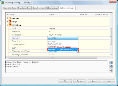
The first thing you need to do is to change a setting to make entry of bearings as degrees minutes seconds much easier. If the Civil 3D toolspace is not already visible, type showts and press enter at the command line. Select the Settings tab, then right click on the drawing name and select "Edit Drawing Settings...". Select the Ambient Settings tab.
In the Property column, scroll down to the section labeled Direction. Verify that the Unit Property is set to degree, then lft click on the value column next to the property labeled Format. It may be currently set to "decimal" or something similar. Left click on the value a second time and a drop down list will appear. Select DD.MMSSSS (decimal dms) from the list, then Apply and OK.

Start the polyline command and pick your start point. At the command line, type 'bd to enter the bearing-distance transparent command. The command line will prompt you to select a Quadrant.Quadrants - NE = 1, SE = 2, SW = 3, NW = 4
Press 1 for Northeast then press enter. The next prompt is requesting the bearing. Just above the >>Specify bearing: prompt in the command line, you can see that the current direction unit is set to degree, Input : DD.MMSSSS (decimal dms) because of the change we made in the ambient settings. To input the bearing 15d17'32" in the DD.MMSSSS (decimal dms) format, just type 15.1732 and press enter. [WOW, isn't that way easier?] The final prompt is to >>Specify distance: (500.00 for this example) then press enter.
Civil 3D will now calculate the coordinates for this bearing and distance and feed it to the command line. This in turn will draw the line or segment of the polyline before returning to the prompt for the next quadrant.
So what happens when you mistakenly type in the wrong quadrant, bearing, or distance? If you're creating a polyline, then you can just use undo that's built into the polyline command. Here's how it works:
After completing the prompts with the wrong information, press the escape key one time. This will get you out of the transparent command and back to the normal polyline command line prompt. At that point, you can type U and press return. This will remove the last segment of the polyline that was just created. Then just type 'bd and press return to enter additional bearings and distances. You can also escape back to the polyline command to change between arc segments and line segments.
6 comments:
i don't think this fixes the problem even in 2009 civil 3d
http://discussion.autodesk.com/thread.jspa?threadID=663727
Allen
Allen,
I tried it in both 2008 and 2009 and it seems to work as expected. That makes me think that there has to be a setting in your drawing or template that's different from the one I'm using. If you don't mind, please try this:
1. Create a new drawing from an OOTB template such as _AutoCAD Civil 3D (Imperial) NCS Base.dwt.
2. On the Ambient Settings Tab scroll down to DIRECTION (NOT ANGLE) and change the Format to DD.MMSSSS (decimal dms).
3. Now draw the polyline from 0,0;'bd; 3 (quadrant); 15.1417 (angle/bearing); 500 (ft); [enter]; [enter]; zoom extents.
4. Menu: Lines/Curves; Add Line/Curve Labels; Add Line/Curve Labels.
5. From the Add Labels dialog box: Add; Select the polyline drawn in step 3.
If you get the correct result using this template, then the problem is definitely a setting in your drawing or template. Verify that the drawing units (command: units) for Type are set to "Decimal Degrees" and the Drawing Settings - Angular Units are set to Degrees then try again.
If it still doesn't work, let me know and I'll see if I can find any other settings that might be causing the problem.
it is now when i draw a bearing and distance. it is when i draw a line by angle that it does nor do it correctly. check the post on whe discussion group and see how i have done it and a picture of it.
Sorry, I misunderstood where the problem existed. Try changing the Angle Format to DD.MMSSSS (decimal dms) then draw the line again.
The 'AD transparent command uses the setting in the ANGLE Format.
The 'BD transparent command uses the setting the DIRECTION Format.
See if that fixes the problem. It worked for me when using the OOTB _AutoCAD Civil 3D (Imperial) NCS Base.dwt file and changing the angle format setting. I checked it with a general curve label style and with two AutoCAD angular dimensions (one in Decimal degrees, and the other in Deg Min Sec format).
I'm a surveyor, and this did indeed fix the problem Allen was describing. Thanks!
Glad I was able to help. :D
--Tommie
Post a Comment