Have you ever wanted to offset a line multiple times within one command? See how after the jump...
A blog about AutoCAD and AutoCAD Civil 3D for civil engineering professionals.
Wednesday, September 21, 2011
Thursday, September 15, 2011
Properties vs List - Same or Different?
Though the properties palette is packed with information, there may be something missing. Here's an example of information that the list command reports that isn't available in the properties palette:
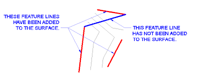
In Figure 1.0, there are four feature lines. The three red feature lines have been added to the surface, but the fourth feature line (the blue one) has not been added to the surface. How do I know that? It's all in the properties...just not the properties palette.
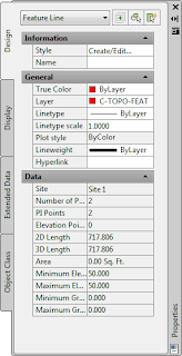
Figure 1.1 shows the information that is available in the properties palette for a feature line that has been added to a surface (such as one of the red feature lines in Figure 1.0):
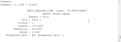
If I run the list command on the same feature line (one that has been added to a surface), Figure 1.2 shows the information that is provided in the command line:
Notice that for this Civil 3D object, the properties in the "General" section of the properties palette don't appear in the list command results. Though some of the "Data" section of the properties palette is being reported in the list command results, a very useful property, "Breakline Data", only appears in the list command results and not in the information reported in the Properties Palette. The "Breakline Data" property lists the surface that contains the feature line definition in it and the breakline set. This information could be important if you need to delete this feature line but want to know if deleting the feature line will affect your surface definition.
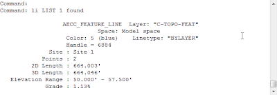
Figure 1.3 shows the properties of a feature line that has not been added to a surface (such as the blue feature line in Figure 1.0).
Notice that for this feature line, the "Breakline Data" property has been omitted from the list command results. That's how I know that this feature line has not been added to a surface definition in this drawing.
In Figure 1.0, there are four feature lines. The three red feature lines have been added to the surface, but the fourth feature line (the blue one) has not been added to the surface. How do I know that? It's all in the properties...just not the properties palette.
 |
| Figure 1.0 |
 |
| Figure 1.1 |
 |
| Figure 1.2 |
Figure 1.3 shows the properties of a feature line that has not been added to a surface (such as the blue feature line in Figure 1.0).
 |
| Figure 1.3 |
Wednesday, September 14, 2011
Get Those Child Styles Under Control
Have you ever created a child style, changed a setting on it, then wished that component property was still following the default setting from the parent style? This is especially apparent when changes are made to the Text Contents of a component. Before you go blaming the software for not working correctly, take a look at the style itself. It may be doing exactly what you told it to do.
Once you make a change to any part of a component of a style, an override is flagged on the Summary tab and that part of the component will no longer follow the changes made to the parent style. Here's a short exercise to show how it works:
Now to see how this change affects the parent style, edit the original label style. You can do this by repeating Step 3, then selecting the Summary tab. Left click on the by Component 2 and you'll see a gray arrow pointing down in the Child Override column. This indicates that this property has been overridden in at least one child style. If you want to remove this override from all the child styles, left click on the gray arrow. A small red x will appear near the bottom right side of the gray arrow to indicate that you will be removing these overrides. Left click on Apply. The Summary tab will refresh at this point and all expanded properties will collapse. Left click on the
  by Component 2 again and there should no longer be a gray arrow in the Child Override column of the General: Visibility row. You can edit the child style to verify that the Visibility of Component 2 was reset to True.
The point of this exercise was to show you how and when the overrides are created so that if your child style isn't responding the way you expect when a change is made to the parent style, take a look at the Summary tab and look for Overrides.
Once you make a change to any part of a component of a style, an override is flagged on the Summary tab and that part of the component will no longer follow the changes made to the parent style. Here's a short exercise to show how it works:
- Create a new drawing from the "_AutoCAD Civil 3D (Imperial) NCS template" in Civil 3D 2012.
- In the Toolspace, Settings tab, locate the Structure Label Styles.
- Expand the Label Styles and select the label style named "Data with Connected Pipes (Sanitary)", right click, and choose Edit... from the list.
- After the Label Style Composer dialog box is open, select the Layout tab and verify that there are three components in this style: Structure Text, Incoming Pipes, and Outgoing Pipes.
- Now close this dialog box by left clicking on Cancel.
- Locate the Structure Label Style in the Toolspace Settings tab again. This time right click on the "Data with Connected Pipes (Sanitary)" style and choose "New..." from the list.
This will create a child style of the selected label style. - In the Label Style Composer dialog box, select the Information tab and edit the Name to: "Data with Connected Pipes (Sanitary) [Description Only]". You can also edit the Description for this label style on the Information tab at this time.
- Now select the Layout tab, then in the Component name: dropdown list, select "Incoming Pipes".
- Under the "General" section, locate the "Visibility" property . Change the value to False.
- Repeat this process for the Outgoing Pipes component too.
- Now select the Summary tab. In the Property column, left click on the
by Component 2 to expand the properties of that component.
Now to see how this change affects the parent style, edit the original label style. You can do this by repeating Step 3, then selecting the Summary tab. Left click on the
The point of this exercise was to show you how and when the overrides are created so that if your child style isn't responding the way you expect when a change is made to the parent style, take a look at the Summary tab and look for Overrides.
Tuesday, September 13, 2011
Multiple Surface Dilemma (Part 3)
NOTE: This is Part 3 of the Multiple Surfaces Dilemma Series. You can view Part 1 of the series here. In Part 1 of this series, a surface named ComboSurface was created. Make sure
you create that surface in your drawing before proceeding with these
steps.
Wouldn't it be nice to have a visual representation of the target minimum depth in the profile view while you're designing your pipe network? Here's a way to make that happen:
Create a new surface in your current drawing and name it "MinimumDepth". You can use the same procedure as described for creating the "ComboSurface" in the original post of this series. Just as with the ComboSurface, this surface will not need to be displayed so set the surface style to "_No Display" as it's created.
To add some substance to the new surface, you'll need to paste the ComboSurface into the MinimumDepth surface. Again, use the same procedure described in the original post of this series except you'll be pasting a different surface.
Under the MinimumDepth surface definition, locate the Edits option, right click, and select "Raise/Lower Surface".
When prompted at the command line, enter -4 to lower the MinimumDepth surface 4 feet.
The last thing to do is create a profile based on the MinimumDepth surface:
- On the home ribbon tab, locate the "Create Design" Panel, left click on Profiles, then choose "Create Surface Profile" from the drop down list.
- In the Create Profile from Surface dialog box, select the alignment, select the MinimumDepth surface, then left click on Add.
- Change the style of the newly created profile to a style called "Minimum Depth". This style places the profile linework on a layer that doesn't plot and has a forced color and linestyle to look different from all other profiles.
Monday, September 12, 2011
Don't Forget These Commands...Part 2
Two AutoCAD Map commands that everyone should know:
MAPCLEAN - A powerful utility that enables you to delete duplicate objects, weed polylines, and do many other cleanup actions.
MAPIINSERT - Inserts a raster image at the location and scale specified in the image or in the associated world file if available.
MAPCLEAN - A powerful utility that enables you to delete duplicate objects, weed polylines, and do many other cleanup actions.
MAPIINSERT - Inserts a raster image at the location and scale specified in the image or in the associated world file if available.
Don't Forget These Commands...Part 3
So I know that I typically blog about Civil 3D, but after assisting with an issue in Microstation this morning, I realized that I should add this keyin command to my "Don't Forget" list.
The issue was that a linestyle looked fine in one drawing, but different when referenced into another drawing. I found some good information on the Bentley site with a quick Google search. Here's a direct link to that page:
http://communities.bentley.com/products/microstation/w/microstation__wiki/setting-linestyle-scale-in-microstation-v8-cs.aspx
We used the keyin command window to set active linestylescale to 20 in both drawings and that fixed the display problem we were having.
So as not to disappoint the Civil 3D readers of this blog, I'll add these commands to the "Don't Forget" list as well. The descriptions are taken from the System Variables.:
LTSCALE - Sets the global linetype scale factor.
MSLTSCALE - Scales linetypes displayed on the model tab by the annotation scale.
PSLTSCALE - Controls the linetype scaling of objects displayed in paper space viewports.
I typically keep all three of these system variables set to 1.
Multiple Surface Dilemma (Part 2)
NOTE: This is Part 2 of the Multiple Surfaces Dilemma Series. You can view Part 1 of the series here. In Part 1 of this series, a surface named ComboSurface was created. Make sure
you create that surface in your drawing before proceeding with these
steps.
In this post, I'm going to assign the ComboSurface to the Pipe Network in the network properties dialog box.
Now as I place pipes and structures in this pipe network, the correct elevation will be used/reported (EG or FG) according to the location of the pipe or structure. Remember, you don't want this surface visible, just create it and select it from the list of surfaces when needed.
In this post, I'm going to assign the ComboSurface to the Pipe Network in the network properties dialog box.
- Since the pipe network has already been created in my drawing, I just need to locate it in the Prospector tab of Toolspace, select it, right click, and choose Network Properties.
- Set the surface name to ComboSurface.
Now as I place pipes and structures in this pipe network, the correct elevation will be used/reported (EG or FG) according to the location of the pipe or structure. Remember, you don't want this surface visible, just create it and select it from the list of surfaces when needed.
Subscribe to:
Comments (Atom)


