There are so many commands in AutoCAD and Civil 3D that we use every day. Some of them are available via toolbars, menus, or the ribbon, that you only have to learn where to find them, not memorize them.
In my case, there are a few commands or system variables that just get lost in the deep void of space inside my brain. Here's a few of them:
LINEWORKSHRINKWRAP - Creates a boundary around a selection set of objects.
PELLIPSE - Setting this variable to 1 will draw an ellipse as a polyline.
FILEDIA - This variable gets set to 0 during some commands and/or lisp routines. If AutoCAD crashes, you may have to reset it to 1 to display dialog boxes instead of command line prompts.
'STAE - Transparent command for Civil 3D to select station from the parent alignment of a profile view.
'SSE - Transparent command for Civil 3D to select station from the parent alignment of a profile view and elevation from a surface.
'PSE - Transparent command for Civil 3D to select station and elevation from a profile view.
'ZTP - Transparent command for Civil 3D to zoom to a point or range of points.
There's plenty more to add to this list, but it's a start.
Friday, May 6, 2011


Thursday, May 5, 2011
Water Structures in Profile View
You know that special symbol for water valves and fire hydrants that the engineers want to see in profile views of water lines? Ours looks something like this:
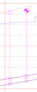
If you think it's a structure style, then you're wrong. It's actually a label style that uses several custom expressions. I use a block that is a rectangle on a no plot layer for the structure in profile view. You can leave the no plot structure visible, or you can turn off the display of the structure in profile view once you've added your labels.
This label will move with the structure, adjust to the size of the structure, and adjust to changes in the surface referenced in the structure. Adjusting the custom expressions, you can control how far all four sides of the rectangle are from the center of the structure based on the size of the structure.
Now if only we could assign a default label style to each structure in profile view I could finish my P&P sheets even quicker. For now, I'm just happy that I don't have to place a dynamic block at each structure then remember to go back and move it as my structure moves to an updated location.

If you think it's a structure style, then you're wrong. It's actually a label style that uses several custom expressions. I use a block that is a rectangle on a no plot layer for the structure in profile view. You can leave the no plot structure visible, or you can turn off the display of the structure in profile view once you've added your labels.
This label will move with the structure, adjust to the size of the structure, and adjust to changes in the surface referenced in the structure. Adjusting the custom expressions, you can control how far all four sides of the rectangle are from the center of the structure based on the size of the structure.
Now if only we could assign a default label style to each structure in profile view I could finish my P&P sheets even quicker. For now, I'm just happy that I don't have to place a dynamic block at each structure then remember to go back and move it as my structure moves to an updated location.
Thursday, March 31, 2011
Multiple Surface Dilemma (Part 1)
Have you ever needed to create a pipe network that involves two different surfaces? Well, I'm going to show you a workflow that could make this situation a breeze.
In this example, I'm working with an alignment that crosses both an existing ground surface (EG) and a finished ground surface (FG). I've already created the alignment and I've added both surfaces via data reference. Here's how it looks so far:
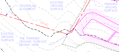
Now, the pipes in this drawing will need to stay a minimum distance below the existing ground surface (EG) until the alignment crosses into the finished ground surface (FG). At that point the pipes will need to stay a minimum distance below the finished ground surface. So how can I do that? I'm going to make a surface that is a combination of those two surfaces.
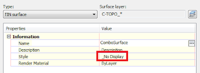
The first thing I'm going to do is create a surface called ComboSurface. In this case, I don't need to see the final product of the combined surfaces, so I'm going to set the surface style to _No Display.
Now I need to add some substance to this surface. I'll do that by pasting the existing ground surface (EG) and finished ground surface (FG) into the new ComboSurface.
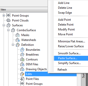
It's okay to select both surfaces at once.
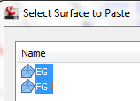
When pasting surfaces into another surface, ORDER IS EVERYTHING! That means I need to make sure that the order is correct. Open the Surface Properties for the ComboSurface and select the Definition tab.
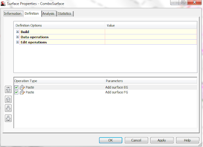 As you can see, the EG surface is at the top of the list and the FG surface is second in the list. This is exactly what I want for this surface. If the order is incorrect, select the EG surface and then left click on the "take me to the top up arrow"
  to send the EG surface to the top of the list.
Next, I need to make sure that this surface is set to Rebuild Automatically. To do this, I select the surface in toolspace, right click, then look for a check mark by Rebuild - Automatic. If there is no check mark ( ), I left click on Rebuild - Automatic to enable this feature. If the check mark is there (
 ), I press ESC to cancel the change.
Now I have a surface that can be used for all the pipes and structures in my network!
In Part 2 of this series, I'll show you how to use this new surface in your pipe network.
In this example, I'm working with an alignment that crosses both an existing ground surface (EG) and a finished ground surface (FG). I've already created the alignment and I've added both surfaces via data reference. Here's how it looks so far:

Now, the pipes in this drawing will need to stay a minimum distance below the existing ground surface (EG) until the alignment crosses into the finished ground surface (FG). At that point the pipes will need to stay a minimum distance below the finished ground surface. So how can I do that? I'm going to make a surface that is a combination of those two surfaces.
The first thing I'm going to do is create a surface called ComboSurface. In this case, I don't need to see the final product of the combined surfaces, so I'm going to set the surface style to _No Display.

Now I need to add some substance to this surface. I'll do that by pasting the existing ground surface (EG) and finished ground surface (FG) into the new ComboSurface.

It's okay to select both surfaces at once.

When pasting surfaces into another surface, ORDER IS EVERYTHING! That means I need to make sure that the order is correct. Open the Surface Properties for the ComboSurface and select the Definition tab.
 As you can see, the EG surface is at the top of the list and the FG surface is second in the list. This is exactly what I want for this surface. If the order is incorrect, select the EG surface and then left click on the "take me to the top up arrow"
  to send the EG surface to the top of the list.
Next, I need to make sure that this surface is set to Rebuild Automatically. To do this, I select the surface in toolspace, right click, then look for a check mark by Rebuild - Automatic. If there is no check mark (
 ), I left click on Rebuild - Automatic to enable this feature. If the check mark is there (
 ), I press ESC to cancel the change.
Now I have a surface that can be used for all the pipes and structures in my network!
In Part 2 of this series, I'll show you how to use this new surface in your pipe network.
Friday, September 24, 2010
3D Faces to 3D Lines
There are many ways to share surfaces between civil software packages. I prefer to use LandXML, but what if that isn't an option? What if the recipient wants the tin to be lines with 3d elevations?
If you export a Civil 3D surface to AutoCAD (or explode it twice), you are left with 3d faces. You can explode them as many times as you want, but you're still left with 3d faces.
Thanks to Google, I found the solution: Regions
In the AutoCAD drawing that contains the 3D faces, execute the region command and select the 3d faces. Now explode the regions that you created and you'll have lines with 3d elevations.
Yes, it's really that simple.
Thanks to Mike Perry for sharing his knowledge on the AUGI forums.
If you export a Civil 3D surface to AutoCAD (or explode it twice), you are left with 3d faces. You can explode them as many times as you want, but you're still left with 3d faces.
Thanks to Google, I found the solution: Regions
In the AutoCAD drawing that contains the 3D faces, execute the region command and select the 3d faces. Now explode the regions that you created and you'll have lines with 3d elevations.
Yes, it's really that simple.
Thanks to Mike Perry for sharing his knowledge on the AUGI forums.
Wednesday, September 22, 2010
The Edit Geometry Panel...It's Not Just For Feature Lines
For those of you that haven't made the jump to Civil 3D 2011 yet, here's a tip for you.
We'll start by drawing a polyline roughly in the shape of a W.
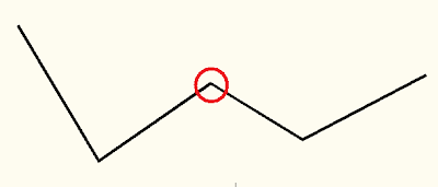
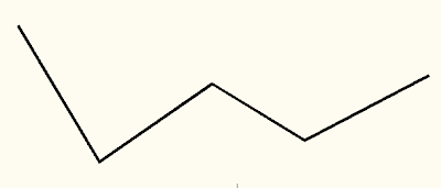 We will now remove the PI inside the red circle.
 Select the Modify Ribbon Tab.
 Now locate the Edit Geometry Panel.
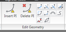
Left click on the Delete PI icon. The command line prompts you to "Select object:", so left click on the polyline to select it. The polyline you select will now have triangles at each PI. These triangles will be gray by default.
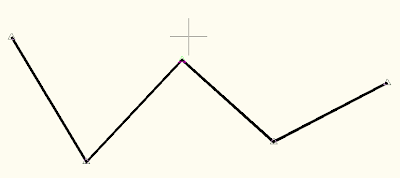
The command line now prompts you to "Specify point:". As you move your mouse near a PI, the gray triangle nearest to the mouse cursor turns green to indicate which PI will be selected.
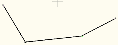
Move your cursor inside the red circle and left click to select the PI you want removed. The selected PI will immediately be removed from the polyline.
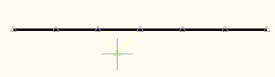
 The Insert PI command works on polylines too. In fact, you can even insert PI's at a specific distance or at a specific increment along the polyline.
 This command sequence works in Civil 3D 2011 too, but there are new enhancements with polylines in AutoCAD 2011 that you might prefer.
We'll start by drawing a polyline roughly in the shape of a W.
 We will now remove the PI inside the red circle.
 Select the Modify Ribbon Tab.
 Now locate the Edit Geometry Panel.
Left click on the Delete PI icon. The command line prompts you to "Select object:", so left click on the polyline to select it. The polyline you select will now have triangles at each PI. These triangles will be gray by default.

The command line now prompts you to "Specify point:". As you move your mouse near a PI, the gray triangle nearest to the mouse cursor turns green to indicate which PI will be selected.
Move your cursor inside the red circle and left click to select the PI you want removed. The selected PI will immediately be removed from the polyline.
 The Insert PI command works on polylines too. In fact, you can even insert PI's at a specific distance or at a specific increment along the polyline.
 This command sequence works in Civil 3D 2011 too, but there are new enhancements with polylines in AutoCAD 2011 that you might prefer.
Subscribe to:
Posts (Atom)