Showing posts with label 2010. Show all posts

Wednesday, September 22, 2010

The Edit Geometry Panel...It's Not Just For Feature Lines

For those of you that haven't made the jump to Civil 3D 2011 yet, here's a tip for you.

We'll start by drawing a polyline roughly in the shape of a W.
We will now remove the PI inside the red circle.
Select the Modify Ribbon Tab.

Now locate the Edit Geometry Panel.


Left click on the Delete PI icon. The command line prompts you to "Select object:", so left click on the polyline to select it. The polyline you select will now have triangles at each PI. These triangles will be gray by default.

The command line now prompts you to "Specify point:". As you move your mouse near a PI, the gray triangle nearest to the mouse cursor turns green to indicate which PI will be selected.

Move your cursor inside the red circle and left click to select the PI you want removed. The selected PI will immediately be removed from the polyline.
The Insert PI command works on polylines too. In fact, you can even insert PI's at a specific distance or at a specific increment along the polyline.
This command sequence works in Civil 3D 2011 too, but there are new enhancements with polylines in AutoCAD 2011 that you might prefer.

Tuesday, August 3, 2010

Trim and Extend. Can’t we do both?

Surely this has happened to you at least once or twice. You run the extend command, but there’s at least one object that needs to be trimmed, not extended. Maybe you ran the trim command and needed to extend a line instead. Never fear because the Autodesk programmers have designed AutoCAD to be multi-talented (thanks guys and gals at Autodesk).

What’s the secret? You can hold the shift key while selecting an object and AutoCAD will run the other command on the selected object.

Here’s an example:
In this image, the red line will be the “cutting edge”. I will trim the green lines and extend the blue line.

At the command prompt, type trim and press enter (or use the trim command found on the Modify ribbon tab in the Modify panel).

When asked to select the cutting edges, left click on the appropriate object(s) or just press enter to select all objects. In our example we’ll select the red line as the cutting edge.

When you are done selecting cutting edges, press enter to continue the command.

At this point, the command line prompts you to “Select object to trim or shift-select to extend…” so we’ll left click on the three green lines to trim them. Now the drawing looks something like this:

To execute the trim command, just hold the shift key while you select the object(s) to be extended. In our example we’ll select the blue line.

One more enter to end the command and the process is complete, using only one command to do two different tasks.

Here’s the final product:

In case you're wondering, this method has been available for several versions of AutoCAD. I guess it pays to read the command line once in a while, even if it is a command that you run all the time.

Thursday, May 13, 2010

Quick Access to My Tools

Are you tired of having to switch to the Home tab to locate the "Freeze" layer icon? If so, here's a nifty little shortcut that you can use:

Locate the icon on the ribbon tab that you want to access.


Now right click on the icon and select "Add to Quick Access Toolbar".


Now the icon will appear in the Quick Access Toolbar at the top left of the AutoCAD (or Civil 3D) program window.

You can see that I've added quite a few icons to mine already.

If you don't like the order of the icons, you can change the order in which they appear in the CUI dialog box.

Wednesday, March 24, 2010

To Fade or Not to Fade...That Might Be Your Question

As I work with a new group of Civil 3D users, I find that some of the new AutoCAD 2010 commands and settings have not been made clear to CAD users at all companies. This week I was able to share XDWGFADECTL with my fellow employees. In case you're in the dark about this command as well, here's the scoop:

One of the things I notice when setting up AutoCAD 2010 or Civil 3D 2010 on a new computer is that drawings containing xreferenced drawings don't look the same as they did when I opened them in previous versions of AutoCAD. Now I'm not talking about having different colors for layers. You can check the layers and you'll still see red, yellow, green, etc. However, an object in the current drawing on a layer that's green looks different from an object in an xreferenced drawing that is also on a layer that's green. Here's an example of what you see with a black model space background:


It does make it very clear what is in the xreferenced drawing and what is in the current drawing, but it can be a bit difficult to see the objects in the xreferenced drawing with a black background such as this. Here are two ways to change this setting.

The first method is to type XDWGFADECTL at the command prompt and set it to 0 (zero) if you want xref objects to appear without fading as seen in previous versions of AutoCAD or Civil 3D.

The second method is through the System Variable Editor:

In the default Civil 3D workspace of Civil 3D 2010, select the "Express Tools" ribbon tab.

Now left click on the System Variable Editor icon.

Once the System Variable Editor dialog box opens, scroll down the list of variables and left click on XDWGFADECTL. The Initial Value is 70 and the Current Value will probably be 70 as well.

Left click in the white box labeled New Value.

Change the value to 0 (zero), but DON'T PRESS ENTER.

Left click on another system variable in the list such as XFADECTL, then left click back on XDWGFADECTL. The New Value should still be set to 0 (zero).

Now left click on the OK command button.

Here's the same text after changing this system variable:

NOTE: This system variable has settings other than a simple "on" and "off" setting. Here's a description and valid values for the XDWGFADECTL system variable:

The XDWGFADECTL system variable controls the dimming for all DWG xref objects. The valid XDWGFADECTL system variable value is between -90 and 90.

When the value is 0 (zero), DWG xref objects are not faded.
When the value is positive, controls the percent of fading up to 90 percent.
When the value is negative, xref objects are not faded, but the value is saved for switching to that value by changing the sign.

Tuesday, March 2, 2010

Why Do You Have To Be Different?

You may think I've dropped off the face of the planet, but I haven't. I'm happy to say that I've embarked on a new career and hopefully that means you, my blog readers, will be learning some new and helpful information in the process. I'll have to discuss my journey from Point A to Point B in another post because right now I have something to show you.

Monday, March 1, 2010, was my first day to officially work as a "Civil 3D Trainer" even though I'm been doing that type of work for years now. As one of my first troubleshooting activities, I was presented with a "problem tree" that wouldn't size correctly. Sounded like a interesting issue to me, so I met with the technician to see the problem firsthand.

The drawing consisted of an existing survey that included Civil 3D points. The marker symbol was not sizing correctly when compared to its peers. In this case, Tree #4987 was supposed to be a size "12", but it sure didn't look like the nearby size "12" Tree #5072.
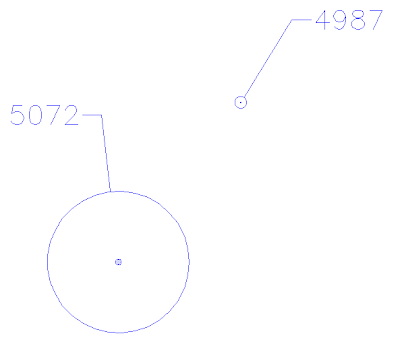
"How did those tree symbols get placed in the drawing?" was my first question. I was told that the tree symbols were a part of the point style. Since all the other trees in the drawing looked correct given the tree diameter size, the problem must be something wrong with that individual point.

So what was wrong with Tree #4987? It was time to take a closer look at these two points by viewing them in the Point Editor Panorama. [You can access this view by selecting the two cogo points and then left clicking on the Edit/List Points in the Modify panel of the COGO Points Contextual menu.]


Here's the Panorama view (some columns were hidden for this image).:
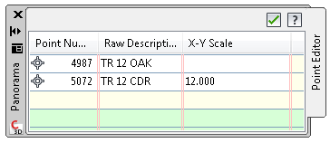
As I reviewed the two points in the list (you may have to use the slider bar along the bottom of the Panorama View to see additional columns), I noticed that the X-Y Scale for the "good tree" point (#5072) was set to the tree diameter size of "12", but the X-Y Scale for the "problem tree" point (#4987) was blank. I suggested that the technician reset the X-Y Scale of tree point #4987 to 12 and the tree symbol for the "problem tree" was immediately updated and now matched the symbol size for Tree #5072.
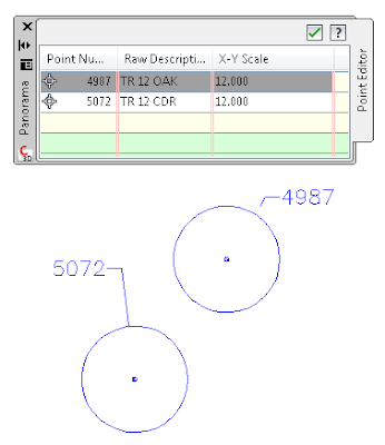
Problem solved!

Despite how easy this solution may seem now, if you didn't setup your template or know the software well enough to know where to look for this solution, you can get real frustrated. Don't let yourself get too stressed about situations like this, just learn where to go for answers.

Answers can be found in places such as the Civil 3D help files, training manuals, your in-house Civil 3D Guru, discussion forums, Civil 3D Blogs, your Autodesk reseller (if you're on subscription), and you might even have to submit a request to Autodesk directly. If your area has a local Civil 3D User Group meeting, get contact info from the "Civil 3D Gurus" that you meet there. Sometimes it's knowing how to phrase the question or using the correct terminology.

There are so many resources available to us that we sometimes overlook. Be diligent and keep working at it. Civil 3D can work like a well oiled machine if you work with it, not against it.

Good luck with your next Civil 3D problem and use the resources you have available. Most of the time the answer is out there, somewhere, just waiting to be found.

Monday, February 9, 2009

Do You Have What It Takes?

If you think you have what it takes, or even if you just want to get a jump start on the new technology, Jack Strongitharm (otherwise known as Junction Jack), has blogged instructions on how to join this year's beta test program for Civil 3D. It's not too late to test the new features before the final product hits the shelf, but you better make it fast.

AutoCAD 2010 AEC Press Release Webcast

Here is a link to view the recorded Autodesk 2010 AEC Press Release Webcast. You can also download the AEC 2010 Launch Press Materials. The zip file contains information on the following Autodesk 2010 products:
  • AutoCAD Architecture 2010
  • AutoCAD Civil 2010
  • AutoCAD Civil 3D 2010
  • AutoCAD Map 3D 2010
  • AutoCAD MEP 2010
  • AutoCAD Raster Design 2010
  • AutoCAD Revit Architecture Suite 2010
  • AutoCAD Structural Detailing 2010
  • Autodesk MapGuide Enterprise 2010
  • Autodesk Navisworks 2010
  • Autodesk Revit Architecture 2010
  • Autodesk Revit Structure 2010
  • Autodesk Robot Structural Analysis 2010

Friday, February 6, 2009

AutoCAD 2010 Product Demo Videos

For a quick look at some of the AutoCAD 2010 PDF capabilities that I discussed yesterday, there is a video posted on YouTube.

Additional AutoCAD 2010 Product Demo Videos can be found here.

Thanks to Shaan for posting this one.

2010 Product Launch

You can view recorded videos and download the 2010 Launch Press Materials here. There will be additional press releases today for the verticals (including Civil 3D). The videos will be posted and ready to view by everyone early next week using the same link.

Be sure and check Shaan's Between the Lines Blog for a link to today's webcast at 11am EST. Today's webcast will include a look at the Architecture, Engineering, Construction, Utilities and Geospatial 2010 Autodesk Product Line. This includes a look at Civil 3D.

Also, the AutoCAD 2010 Launch Press Materials zip file includes some information on Civil 2010 (not Civil 3D 2010) since this product is built on AutoCAD, not AutoCAD Map. Hmmmm, might this be a sneak peak at Civil 3D 2010? We'll find out later today.

Thursday, February 5, 2009

AutoCAD 2010 Is Finally Unveiled

I hope many of you were able to view the Autodesk 2010 Product Release Webcast today. If not, Shaan Hurley has posted a link to the webcast on his blog. The webcast was recorded and can be viewed by anyone willing to provide your name, company name, email address and accept the privacy statement. There will be another webcast on Friday, February 6, at 9:00 am PST. Details can be found on Shaan's Between the Lines blog. This second webcast will cover Architecture, Engineering, Construction, Utilities, and Geospatial.

Today's webcast showed some of the great new features of AutoCAD 2010. Some of these features were available to Autodesk Subscription Customers with AutoCAD 2009 such as PDF overlays and 3D printing. Since the majority of my work is with a vertical (Civil 3D), I was unable to enjoy these cool new features. These features are now fully integrated into AutoCAD 2010 and that means they will also be included inside of Civil 3D 2010.

My two favorite features of today's webcast are PDF's created by AutoCAD and parametric drawing constraints. I know we've been able to plot to PDF for several releases now via either an AutoCAD pc3 file or third party applications (both free and paid versions). However, let's see those third party applications do what AutoCAD 2010 is doing with their PDF's. Here's a list of a few things you can do with PDF's created by AutoCAD 2010 that were shown in today's webcast:
  • Create PDF's that include layer information
  • Overlay PDF's in a manner similar to images or DGN's
  • Change the transparency of the linework shown in a PDF overlay
  • Snap to geometry points of the linework shown in a PDF overlay
  • Change the visibility of the linework shown in a PDF overlay
  • Clip the PDF overlay similar to xclip with an attached drawing
  • Modify the clip boundary on a PDF overlay
  • Invert the clip boundary on a PDF overlay
  • Lines merge or lines overwrite option
  • Text can now be embedded into the PDF so you can search for text
Now honestly, I'll bet you can't wait to go check out AutoCAD 2010 for yourself. Be sure and keep your eyes on the CAD media, because there are more things being unveiled in the upcoming days.