Monday, March 28, 2016

Point to Point Inverse in Civil 3D

I find that map commands in Civil 3D can be very useful for both land surveyors and civil engineering technical staff. The problem seems to be that many users don't know about these very useful commands.

Here's a question than I'm often asked by land surveyors:
Is there a point to point inverse in Civil 3D?

The answer to this question is YES!
CGSLIST + the 'PN transparent command.

CGSLIST

CGSLIST is located on the Analyze ribbon tab in the Inquiry panel.


BEFORE YOU BEGIN

The help information for this command doesn't mention vertical difference, but that information is included in the output for this command.


This command uses the settings for Angle, Distance, and Direction that are stored in the Ambient Settings of the current drawing. If you want the course (bearing) to be in N90°00'00"E format, open the Drawing Settings dialog, choose the Ambient Settings tab, change the Direction > Format setting to DD°MM'SS" and press OK. You can also change the precision for coordinates, distances, and more.


You should also expand the command line so that you can see at least five lines of the command line history.


My example begins with a drawing that contains two points that are exactly 10 feet apart horizontally and 5 feet apart vertically. This allows me to confirm the horizontal and vertical results of the command.

Using the CGSLIST Command

  1. After selecting the Analyze ribbon tab, locate the Inquiry panel and click on the List Slope (CGSLIST) icon.


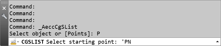
  2. When prompted, type P and press enter to use the Points selection option. Selecting the Points option here only notifies the command that you want to select coordinate points, not Civil 3D cogo points, for the input data type. 
  3.  

    NOTE: The command line shows that _AeccCgSList is the command running. You can also access this command by typing CGSLIST at the command line and pressing enter. If you are using Map 3D, use MAPCGSLIST. All three commands work in Civil 3D version 2015 or later. 

  4. When prompted to select a starting point, type 'PN and press enter. This will tell the command that you will be entering Civil 3D cogo point numbers instead of selecting coordinate points by clicking on the screen.


  5. When prompted to enter a point number, enter the starting cogo point number then press enter.


  6. The coordinates of the cogo point will appear in the command line history. Now enter the next cogo point number for the ending point then press enter.


  7. This command reports horizontal distance and elevation difference. It also reports the point elevations along with the grade and slope between the points. Notice that the distance shown is a horizontal distance, not a slope distance which is the result reported when using the DISTANCE or MEASUREGEOM command.

Now...
Don't be fooled!

Even though the command shows that the 'PN transparent command is still running, the CGSLIST command has reverted to the original Select object or [Points] prompt. At this point you'll need to press ESC to exit the 'PN transparent command, type P then enter to return to the Points selection, and finally type 'PN and press enter to return to the 'PN transparent command.

If you want a command that repeats with the 'PN transparent command, record a macro. If you're interested in a follow-up blog describing how to create and use that macro, please let me know in the comments section of this posting.

Wednesday, February 18, 2015

Where Do You Think You're Going?

I saw an interesting issue today with a General Line Label. Here's how it looked in the source drawing. A user imported a general line label style and added the label to an existing AutoCAD object in the new drawing. The problem was that the arrowheads were pointing in the wrong direction. It looked similar to this label.

A General Line Label with arrowheads at each end of the segment with the incorrect rotation angle.

I compared the style settings between the source and destination drawing. Everything matched exactly. The only difference between the original label and the new label is that the original label was on a polyline and the new label was on a line that had an elevation of 500 for one endpoint and an elevation of 0 for the other endpoint. Once I set one endpoint elevation to match the other endpoint (both at elevation 0), the label then looked exactly as it was designed to look.

A General Line Label with arrowheads at each end of the segment with the correct rotation angle.

Lesson of the day #1: Sometimes polylines are a better choice than a line for labeling.

Lesson of the day #2: OSNAPZ to the Rescue.

Monday, December 8, 2014

Resize Me!

Sometimes you learn things that you don't realize others haven't seen yet. During the CV6726-P - Attack of the Roundabouts: Conquer Them with Vehicle Tracking class taught by Brian Levendowski, Infrastructure Industry Manager, CAD Technology Center, Inc., I found this to be the case with resizing of viewports in the Model tab. When Brian did this during his presentation, the previously silent classroom was filled with Oohs and Aahs and the sound of pencils/pens and paper immediately followed. Since so many in that class had not seen this feature I decided to share it with you.

Here is the step by step description.
  1. Open any drawing with version AutoCAD 2015 or later, then set the View ribbon tab current. This also works in verticals such as Civil 3D.
    Select the View Ribbon Tab
  2. Locate the Model Viewports panel and left click on the words Viewport Configuration to activate the drop down selection list.
    Accessing the Viewport Configuration drop down selection list.
  3. From the drop down selection list, left click on Two: Vertical (or any other option except Single) to view multiple viewports on the Model tab of your current drawing.
    Select a viewport configuration with multiple viewports.
  4. With the multiple viewports visible, you can now hover your cursor over any of the adjoining lines between viewports, left click, hold, and drag to the desired location. When you get the line moved to the desired location, release the left mouse button.
Here's a video that shows these steps in action.


You can also add viewports by using the + as the beginning point of the left click, hold, and drag location. By dragging an existing viewport near another viewport boundary you can delete an existing viewport. To see this in greater detail, I refer you to Greg Battin's AutoCAD Tips blog post titled AutoCAD 2015 Resize Model Space Viewports.

Monday, December 1, 2014

Autodesk University 2014

After several years away from Autodesk University, I'm looking forward to attending this remarkable event. I'm currently at Austin-Bergstrom Internation Airport awaiting the arrival of the plane that is scheduled to take me to Dallas where I will catch a flight to Las Vegas.

I was pleasantly surprised to see how many USB and AC outlets were available for use at the airport this morning. I even found an opening at a table with said outlets so it's even easier to use my heavy, but hopefully powerful enough, new workstation laptop. Arriving for an early morning flight meant I missed all of the US 183 morning traffic. However, the two hours of sleep I got will probably mean nap time during the flight from DAL to LAS.

Another bit of good news is that I'm still a Time Warner Cable subscriber. Though I have my complaints, especially price, I am currently enjoying the free use of the Boingo WiFi HotSpot at the airport. I'm glad I at least scan the many emails I receive from TWC throughout the year that notified me of this customer benefit.

I'm awaiting the arrival of Ishka (@C3Dish). His flight is a later one that mine so he got to sleep later than I did this morning. I'm jealous of that extra sleep right now. He and I were hoping to be on the same flight today. Unfortunately the price difference was too much compared with what his employer was offering to pay. Hopefully next year we can both get approval for the trip sooner so we can schedule our flights together. We both would enjoy discussions of Civil 3D, InfraWorks 360, and 3DS Max during the flight.

I spent some time yesterday reviewing my schedule and checking for available classes one last time. I've heard many times that an opening in a lab can be found if you keep checking. Yesterday that actually happened to me. I saw an opening in the CM8257-L - AutoCAD Customization Boot Camp: Beyond the Basics Repeat lab. Though I hadn't initially planned on taking this lab, I changed my mind once I read about it. I was looking forward to finally attending a lab this year until I got a scheduling conflict. I decided to pay it forward by selecting this lab and dropping my two lab selections that were in conflict with another event that I wanted to attend. I hope the recipients of my seats enjoy the labs.

I look forward to attending Curt Moreno's CM6160 - Standards for Developing Standards: A How-to for Busy CAD Managers instead. It's probably a better choice for me anyway. I only wish there had been some documentation to review before the class.

I can't wait to arrive in Las Vegas and get registered. There are a few presentations on my schedule for today that should be interesting including:
  • CV6443-P - INFSYM: BIM Best Practices for Designing Better Water Systems
  • CV6627-P - INFSYM: Regional Land Development and Land Planning Projects Best Practice Workflows
  • UT6664 - INFSYM: Did We Build It Right? Utility Project Construction and Collaboration 
They are calling boarding for my flight so I'll see you in Las Vegas!

Wednesday, January 8, 2014

I Got Shifted!

For those of you venturing into the Infrastructure Design Suites that include Raster Design, you might experience an unexpected "feature":

What happened to my shift key?

When working in Civil 3D, I use my shift key quite often. When I began using Civil 3D (with Raster Design installed), I noticed that my shift key seemed to no longer be working in two specific situations, though there may be others as well.
  • Hold shift and select an object to remove it from the current select set
  • Hold shift and select an object to switch between extend and trim commands
The shift key still worked in other cases such as shift+right click to access the osnap right click menu so I was a bit perplexed. Thankfully Mark Martinez with Enceptia knew right away how to fix the problem.

If you have Raster Design installed, there is a special setting that allows you to select an image by holding the shift key and selecting anywhere in the image. This setting can be very useful unless you need to use the shift key for other purposes such as those I listed. Mark instructed me where to disable the Shift+Left click feature that Raster Design has enabled by default. Here's the solution:
  1. At the command line, type ioptions and press enter.
  2. On the User Preferences tab, left click on the check mark by "Shift+Left click image select" to disable this setting.
  3. Left click on OK to apply the setting change.

  4. Select. Left click to disable. OK.
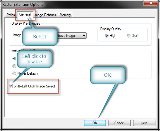
  5. At the command line, type mapioptions and press enter.
  6. On the General tab, left click on the check mark by "Shift+Left Click Image Select" to disable this setting.
  7. Left click on OK to apply the setting change.

  8. Select. Left click to disable. OK.
Hopefully this will keep you from pulling out your hair as I was tempted to do.