Unfortunately, the answer from Autodesk web support is usually that you'll have to go to a backup or rebuild the pipe networks from scratch. Well, I found something this week that might help the process of re-creating those pipe networks.
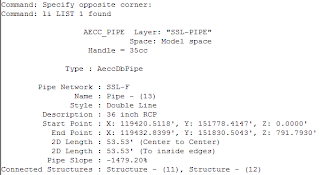
If you list one of the corrupt pipes, you'll notice that there is no "Pipe Network" reference in the "corrupt" pipe. The first image is a sample of a "good" pipe, the second image is a sample of a "corrupt" pipe.


You could use the plan set (if you have one already) to recreate the pipe network, but if you don't have one, here's another way.:
Create a pipe style that shows only the Plan Pipe Centerline and the Plan Pipe End Line. Also create a pipe label style that shows the inside pipe diameter. The pipe ends will assist you in knowing where the pipes begin and end and the centerline will give you an elevation for the pipe. You should also label the structures so that you'll know which one to place.
Now you can create the pipe network by layout snapping to the endpoints of the pipe centerline for elevation and changing the pipe sizes as necessary based on the inside pipe diameter label.
Obviously, this isn't a cure-all and it will still take some time to complete, but hopefully it might help you get back up and running a little bit quicker.
No comments:
Post a Comment