Sunday, April 27, 2008

How Many Inches in a Meter?

I know that the easiest way to convert your existing template to a new version of Civil 3D is to just open and save the template. However, you will be missing some of the new settings that just got implemented into the new version of the software.

One of these new settings can be found in the Drawing Settings dialog box, Units and Zone tab. There is a new "Imperial to Metric conversion" setting there. It defaults to "International Foot(1 Foot = 0.3048 Meters)" for the OOTB templates. This means that when you open and save your existing template, it will also be set to "International Foot".

So depending on your location and project, you might need to change this setting to "US Survey Foot(39.37 Inches per Meter)".


Although it could be found in previous versions, you may not know that there is a similar setting in the Land XML export settings under the Data Settings properties.

Friday, April 25, 2008

*Warning* Multiply owned object

Since I'm already having to use this in Civil 3D 2009, I'm going to post it here so it's easier for me and others to find in the future.

Isn't it frustrating when you get this type of warning message?
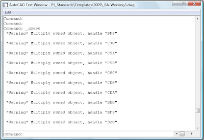

Great. Now what do I do? Is the drawing corrupt? Do I have to start from scratch?

Some discussion forum posts suggest that wblocking the drawing can help. Yes, it does get rid of the warning messages, but you could lose all your styles, object layer settings, defaults, etc. That's not acceptable.

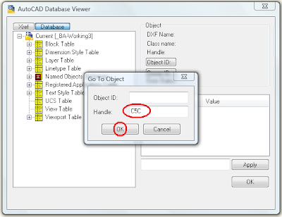
Well, according to Scott's Superman post, there is a command you can type to get rid of the problem object (Replace C5C with the handle shown in your command line):

(entdel (handent "C5C"))

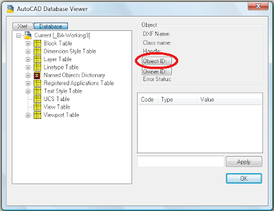
Since it is possible to lose a style or two by running this command, I'd like to know what I'm deleting. So after a bit more research, I found a link to Shaan Hurley's post about DbView for AutoCAD 2007. I followed the instructions and ran the program. It works with Civil 3D 2009. I only wish someone could a "delete" command button for the selected object.

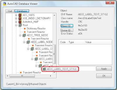
Here's a few screen captures of the DbView program in action:


At this point, I would love to give you some great and wonderful insight as to what you're seeing in that last image. Unfortunately, for now all I can do is look at it and see what type of object will be deleted.

As far as deleting the object goes there are several options for running the command from Scott's post.

  1. You could edit the handle number in a text document, then paste it into the command line.
  2. You could also create a script file on your desktop. Then you would just edit the handle in the script file, save and close, then drag and drop the script file into AutoCAD. You'll need to either put a space after the final )) or make sure and add a return after the final )) in the script file or you'll have to hit enter after running the script file.
  3. Running this command through a lisp routine is another option.
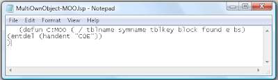
It seems to me that every time I've seen this warning message, it's always been when I have been dragging styles between drawings. In Civil 3D, it definitely happens when you drag child styles into a drawing that already contains the parent style. This happens even if the parent styles were just created by dragging them from the same drawing. Hopefully it can be fixed with C3D 2009 SP1.

Thursday, April 10, 2008

Google Map Street View

Go to the google maps website: http://maps.google.com

Click on Street View to see the locations where street views are available.


Type in a street address including city and state. If a street view is available, there will be a small image of the street view at that address.

Click on the image and you will see an enlarged image of the street view at this address.

There are several arrows denoting directions you can move up or down the street.

You can also rotate right, left, zoom in, and zoom out using the icons

Try this one as an example.

549 S Lamar Blvd Austin TX

Left click on the image shown, then select the rotate right icon.

You will now see the street view of the Central location of Bicycle Sport Shop in Austin, Tx.

In this example, you can also select from N (north) on S Lamar Blvd or S (south) on S Lamar Blvd.

Special thanks to Mark R. for showing me this one.

PVLS PART 4: Offsetting a Profile View Label

This is Part 4 of a series on Profile View Label Styles (PVLS). This post may not make a whole lot of sense if you haven't seen the previous posts in this series. Please take a moment to read them before continuing to read this one. Here's a link to each:

PVLS PART 1: Creating Profiles for Labeling Crossing or Connecting Pipe Flowline Elevations

PVLS PART 2: Creating the Style for the Connecting Pipe Flowline Elevation Label

PVLS PART 3: Labeling the Crossing or Connecting Pipe Flowline Elevations

To use the Offset Style created in this series, you'll need to create the label style first. (Instructions for creating an offset label style can be found Part 2 of this series.

After the style has been created, right click on the style and select New... in the Settings tab of the Toolspace. For Profile Views, this will create a "Child" of the original style. It will have all the same properties and components of the original style at the time that it is created except those that you change.

On the Information tab, rename the text inside the brackets [child] to [RT-0.3]. That means that we will be creating a style that moves the text right 0.3 inches. Go ahead and left click on Apply then select the Layout tab.

Remember how we deleted the original text so that the first component was "Line for Text". This is where it comes into play.

Go to the Line section and change the Start Point X Offset to 0.3, then Apply and OK. Now place the style in the drawing or change one of the existing labels to use this style instead. Here's a screen capture of the original parent style and the new offset RT child style.


There are other ways to change the style as well. Try changing these values and see how they affect the style:
  • The length of the "Line at Insertion Point"
  • The length of the "Line for Text"
  • The Start Point Y Offset of the "Line for Text"
You should never change the values of the "Offset Connection Line", because they will always follow the start/end of the other lines in the style.

Well, that's it for my series on Profile View Label Styles. I hope you found it useful. Feel free to post a comment if you have questions or if you just want to request a topic for a future post.

Technorati Tags:

PVLS PART 3: Labeling the Crossing or Connecting Pipe Flowline Elevations

This is Part 3 of a series on Profile View Label Styles (PVLS). You should also read Part 1 and Part 2 of this series for additional information.

To label a crossing and/or connecting pipe flowline elevation, you'll need the style created in Part 2 of this series and profiles for both the main line and the crossing/connecting pipes as described in Part 1 of this series.

After you have the style and profiles created in your drawing, the rest is really simple.
  1. Zoom into the connecting pipe that you want to label.
  2. From the Civil 3d Profile menu, select "Add Profile View Labels", then "Add Profile View Labels...".
  3. In the Add Labels dialog box, select the style that you created from Part 2 of this series (mine was called Connecting Pipe Label).
  4. Choose a Marker style if you want one. I don't generally use one for this style.
  5. Left click on the Add command button.
  6. You will be prompted to select a profile view. Select the profile view by left clicking on one of the grid lines, not the actual profile.
  7. When asked to specify a station, select the endpoint at the flowline of the crossing pipe shown in the profile view.
  8. When asked to specify an elevation, you can either select the same point or specify an elevation for the insertion point of the label.
  9. Repeat this process for other connecting pipe labels that are visible in this profile view.
  10. If you need to add labels in other profile views, you'll need to left click on the Add command button again to select a different profile view.
So now the label is placed, but there aren't any elevations shown. Here's the secret:
  1. Select all the connecting pipe labels in one profile view and then look at the properties listed on the labels. There is a Civil 3D section that contains a listing for Profile1 Object and Profile2 Object. They will be set to by default.
  2. Left click on the for Profile1 Object and set that to the profile you created for the flowline of the main pipe.
  3. Left click on the for Profile2 Object and set that to the profile you created for the crossing and/or connecting pipes and pipe size changes.
Now you have the flowline elevations and all you have to do is editlabeltext on the style to change the name of the utility line and modify the pipe sizes. As I said in my first post, I'm sure you can take this style further to get the pipe sizes in it. Also, you would need to make a copy of the style and modify the text for grade breaks, and crossing pipes.

Well, that's it for Part 3. In Part 4, I will describe how to use the offset capability that we put in place when we created the Profile View Station Elevation Label Style in Part 2 of this series.

Technorati Tags: