You can view recorded videos and download the 2010 Launch Press Materials here. There will be additional press releases today for the verticals (including Civil 3D). The videos will be posted and ready to view by everyone early next week using the same link.
Be sure and check Shaan's Between the Lines Blog for a link to today's webcast at 11am EST. Today's webcast will include a look at the Architecture, Engineering, Construction, Utilities and Geospatial 2010 Autodesk Product Line. This includes a look at Civil 3D.
Also, the AutoCAD 2010 Launch Press Materials zip file includes some information on Civil 2010 (not Civil 3D 2010) since this product is built on AutoCAD, not AutoCAD Map. Hmmmm, might this be a sneak peak at Civil 3D 2010? We'll find out later today.
Friday, February 6, 2009


Thursday, February 5, 2009
AutoCAD 2010 Is Finally Unveiled
I hope many of you were able to view the Autodesk 2010 Product Release Webcast today. If not, Shaan Hurley has posted a link to the webcast on his blog. The webcast was recorded and can be viewed by anyone willing to provide your name, company name, email address and accept the privacy statement. There will be another webcast on Friday, February 6, at 9:00 am PST. Details can be found on Shaan's Between the Lines blog. This second webcast will cover Architecture, Engineering, Construction, Utilities, and Geospatial.
Today's webcast showed some of the great new features of AutoCAD 2010. Some of these features were available to Autodesk Subscription Customers with AutoCAD 2009 such as PDF overlays and 3D printing. Since the majority of my work is with a vertical (Civil 3D), I was unable to enjoy these cool new features. These features are now fully integrated into AutoCAD 2010 and that means they will also be included inside of Civil 3D 2010.
My two favorite features of today's webcast are PDF's created by AutoCAD and parametric drawing constraints. I know we've been able to plot to PDF for several releases now via either an AutoCAD pc3 file or third party applications (both free and paid versions). However, let's see those third party applications do what AutoCAD 2010 is doing with their PDF's. Here's a list of a few things you can do with PDF's created by AutoCAD 2010 that were shown in today's webcast:
Today's webcast showed some of the great new features of AutoCAD 2010. Some of these features were available to Autodesk Subscription Customers with AutoCAD 2009 such as PDF overlays and 3D printing. Since the majority of my work is with a vertical (Civil 3D), I was unable to enjoy these cool new features. These features are now fully integrated into AutoCAD 2010 and that means they will also be included inside of Civil 3D 2010.
My two favorite features of today's webcast are PDF's created by AutoCAD and parametric drawing constraints. I know we've been able to plot to PDF for several releases now via either an AutoCAD pc3 file or third party applications (both free and paid versions). However, let's see those third party applications do what AutoCAD 2010 is doing with their PDF's. Here's a list of a few things you can do with PDF's created by AutoCAD 2010 that were shown in today's webcast:
- Create PDF's that include layer information
- Overlay PDF's in a manner similar to images or DGN's
- Change the transparency of the linework shown in a PDF overlay
- Snap to geometry points of the linework shown in a PDF overlay
- Change the visibility of the linework shown in a PDF overlay
- Clip the PDF overlay similar to xclip with an attached drawing
- Modify the clip boundary on a PDF overlay
- Invert the clip boundary on a PDF overlay
- Lines merge or lines overwrite option
- Text can now be embedded into the PDF so you can search for text
Thursday, January 15, 2009
Civil 3D 2009 Update 2 Has Arrived
Just a quick post to let everyone know that the Civil 3D 2009 Update 2 has been posted. You can download this update from the Autodesk website here.
Thanks to Lisa P. for the email notification. I was also notified from Autodesk about the patch after submitting a CER that included my email address.
Another quick reminder to send in your CER's when you crash. It's important for Autodesk to see how often an error occurs and how many folks it affects. This ensures that the problem is given a higher priority level and the chances of it being fixed in the next product update are much greater.
Thanks to Lisa P. for the email notification. I was also notified from Autodesk about the patch after submitting a CER that included my email address.
Another quick reminder to send in your CER's when you crash. It's important for Autodesk to see how often an error occurs and how many folks it affects. This ensures that the problem is given a higher priority level and the chances of it being fixed in the next product update are much greater.
Tuesday, December 30, 2008
Removing A Civil 3D Object Without Using the AutoCAD Erase Command
Sometimes using AutoCAD commands on Civil 3D objects is okay and sometimes it causes problems. For example: deleting parcel segments or pipe network objects. According to Autodesk, deleting a pipe using the AutoCAD erase command has been corrected in Civil 3D 2009, but since I know some of you may still be using Civil 3D 2008 or earlier, I'm going to show you the proper way to delete an object in Civil 3D.
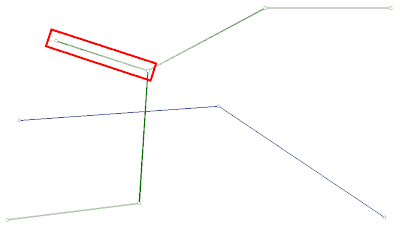
Here I have two pipe networks Water (blue) and Wastewater (green). After a round of revisions, the pipe and one of the structures in the red rectangle needs to be removed.
 I know it's very tempting to just run the erase command and select the structure and pipe to be deleted, but that's what causes the issue. Here's the proper way to delete the structure and pipe.
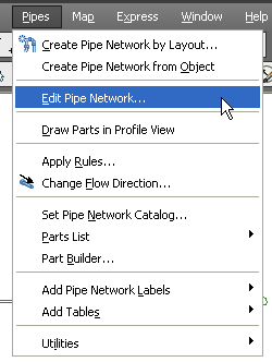
From the Pipes menu list, select "Edit Pipe Network...".
 The command line prompts you to "Select part from pipe network:". After you select the pipe or structure you are deleting, the Network Layout Tools toolbar will appear. The tool you want is the "Delete Pipe Network Object".
 After selecting the "Delete Pipe Network Object" tool, you are prompted to "Select Structure or Pipe". Left click on any structures or pipes that you want deleted from the network.
The reason you should always delete pipe network objects using this tool is because the pipe network part must be disconnected from other parts in the network before they are removed from the drawing.
Something similar happens with parcels so be sure to delete parcel segments using the appropriate tool as well.
[Parcels - Edit Parcel - Edit Parcel Segments]
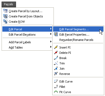 The tool is labeled "Delete Sub-entity".

Here I have two pipe networks Water (blue) and Wastewater (green). After a round of revisions, the pipe and one of the structures in the red rectangle needs to be removed.
 I know it's very tempting to just run the erase command and select the structure and pipe to be deleted, but that's what causes the issue. Here's the proper way to delete the structure and pipe.
From the Pipes menu list, select "Edit Pipe Network...".
 The command line prompts you to "Select part from pipe network:". After you select the pipe or structure you are deleting, the Network Layout Tools toolbar will appear. The tool you want is the "Delete Pipe Network Object".
 After selecting the "Delete Pipe Network Object" tool, you are prompted to "Select Structure or Pipe". Left click on any structures or pipes that you want deleted from the network.
The reason you should always delete pipe network objects using this tool is because the pipe network part must be disconnected from other parts in the network before they are removed from the drawing.
Something similar happens with parcels so be sure to delete parcel segments using the appropriate tool as well.
[Parcels - Edit Parcel - Edit Parcel Segments]
 The tool is labeled "Delete Sub-entity".
Thursday, December 11, 2008
To Link or Not to Link
If you've ever worked with assemblies, you've probably experienced a subassembly not looking the way you initially created it. Now, I don't know what causes it, but I did learn a very simple way to fix it this year at Autodesk University.
Here's the original assembly:
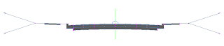 Here's the assembly after a few of the subassemblies took on a mind of their own:
 Even though the assembly will work as expected, it still bothers me that it doesn't visually look correct. Here's how to fix the visual misrepresentation that you're seeing:
Here's the original assembly:
 Here's the assembly after a few of the subassemblies took on a mind of their own:
 Even though the assembly will work as expected, it still bothers me that it doesn't visually look correct. Here's how to fix the visual misrepresentation that you're seeing:
- Select the assembly. The assembly is represented by the green line with a blue circle at it's midpoint in the images shown.
- Right click and select Assembly Properties... from the list.
- In the Assembly Properties, left click on the Construction tab. You must select this tab or the fix won't work.
- Now left click on the OK command button.
Subscribe to:
Posts (Atom)