Tuesday, June 1, 2010
Raster Design OE 2011 has been posted
Thanks to James Wedding for announcing to all his loyal Twitter followers that the Raster Design Object Enabler for 2011 has been posted. There are different installation files for 32 bit and 64 bit operating systems so make sure you install the correct one.


Thursday, May 13, 2010
Quick Access to My Tools
Are you tired of having to switch to the Home tab to locate the "Freeze" layer icon? If so, here's a nifty little shortcut that you can use:
Locate the icon on the ribbon tab that you want to access.
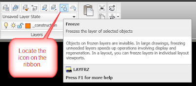
Now right click on the icon and select "Add to Quick Access Toolbar".
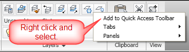
Now the icon will appear in the Quick Access Toolbar at the top left of the AutoCAD (or Civil 3D) program window.
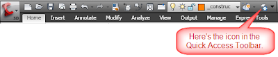 You can see that I've added quite a few icons to mine already.
If you don't like the order of the icons, you can change the order in which they appear in the CUI dialog box.
Locate the icon on the ribbon tab that you want to access.

Now right click on the icon and select "Add to Quick Access Toolbar".

Now the icon will appear in the Quick Access Toolbar at the top left of the AutoCAD (or Civil 3D) program window.
 You can see that I've added quite a few icons to mine already.
If you don't like the order of the icons, you can change the order in which they appear in the CUI dialog box.
Friday, April 30, 2010
New Polyline Grip Editing Options in AutoCAD 2011
It's time to take a look at a couple of the new features in AutoCAD 2011. Today's post will be about polylines. These new features may actually cut down on the amount of times we run the pedit command.
So here's what a polyline looks like when I select it in AutoCAD 2010. You can see the four square grips at the corners.
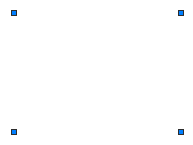
Now let's look at the same polyline in AutoCAD 2011. Did you notice the new rectangular grips at the midpoint of each segment?

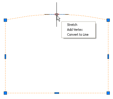
If you hover your mouse over one of these rectangular grips, you'll be given the option to stretch the segment, add a vertex to that segment, or convert the segment to an arc.
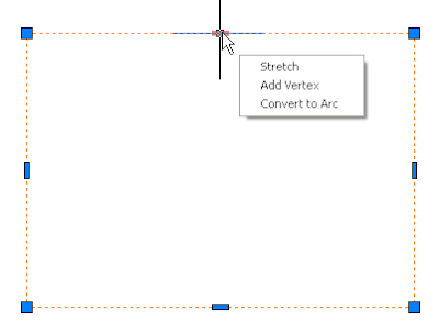
Selecting the "Stretch" option, will allow the segment to "rubber band" or "stretch" to a new location of your choice. You can also stretch the segment by just left clicking on the rectangular grip.
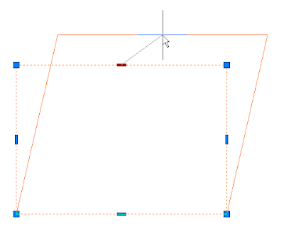
Selecting the "Add Vertex" option will allow you to add a new vertex to the polyline. Note, however, that the segments to the new vertex will be connected to the endpoints on either side of the rectangular grip you selected (the grip is now red).
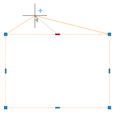
Selecting the "Convert to Arc" option, will convert the segment to an arc and you'll be given the opportunity to select a point on the arc to complete the command.
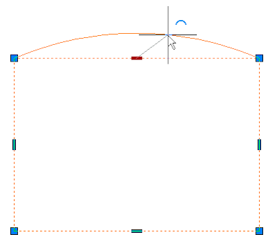
One last thing before we leave the world of polylines, if you hover over the rectangular grip on an arc segment of a polyline, instead of "Convert to Arc", there's an option to "Convert to Line".
I hope these new polyline editing options help you become a more efficient drafter.
So here's what a polyline looks like when I select it in AutoCAD 2010. You can see the four square grips at the corners.

Now let's look at the same polyline in AutoCAD 2011. Did you notice the new rectangular grips at the midpoint of each segment?

If you hover your mouse over one of these rectangular grips, you'll be given the option to stretch the segment, add a vertex to that segment, or convert the segment to an arc.

Selecting the "Stretch" option, will allow the segment to "rubber band" or "stretch" to a new location of your choice. You can also stretch the segment by just left clicking on the rectangular grip.

Selecting the "Add Vertex" option will allow you to add a new vertex to the polyline. Note, however, that the segments to the new vertex will be connected to the endpoints on either side of the rectangular grip you selected (the grip is now red).

Selecting the "Convert to Arc" option, will convert the segment to an arc and you'll be given the opportunity to select a point on the arc to complete the command.

One last thing before we leave the world of polylines, if you hover over the rectangular grip on an arc segment of a polyline, instead of "Convert to Arc", there's an option to "Convert to Line".

I hope these new polyline editing options help you become a more efficient drafter.
Wednesday, April 21, 2010
Navigate This You View Cube
I know my first post about Civil 3D 2011 shouldn't be about how to hide one of the new features, but it's going to be posted by somebody so here you go:
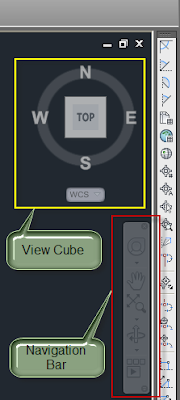
One of the first new things I noticed when I opened Civil 3D 2011 this week was the View Cube and Navigation Bar. While the View Cube is a really cool and useful tool, I don't use it the majority of the time, especially in a 2D view, so for me it's just taking up screen space.
To figure out how to hide this thing (since I couldn't find an X to close it), I searched in the System Variables dialog box for a command to change the view options for this object. You can find the System Variable dialog box in the Tools panel on the Express Tools ribbon tab. I scrolled through the list looking for likely suspects and found some variables beginning with NAV.
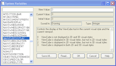
If you select one of the system variables in the list, you'll see a description of what that variable controls and the values that can be set including a description of each option. The Initial Value for NAVVCUBEDISPLAY is 3. That means it is visible in both 2D and 3D visual styles. I figure I only want it to be visible in 3D visual styles so I need to change the New Value to 1 then select OK.
There is also a Navigation Bar that is visible just below the View Cube. You can access the View Cube, the Wheel, Pan, Zoom commands, Orbit commands, and Show Motion in this Navigation Bar. The Navigation Bar and View Cube both have transparency settings that you can control so that you can still see drawing objects behind the tool, you just can't select an object at a location that is within the bounds of the Navigation Bar or the View Cube, for example.
If you view your drawings from multiple views such as Top, Front, SW Isometric, etc., keep this View Cube visible and use it. It works very well and is intuitive to use. If you only draw in 2d or might view something in 3d maybe twice a year, then maybe you should go ahead and change the NAVVCUBEDISPLAY value to 0 or 1.
The Navigation Bar has a very small x in the top right corner that can be used to close the toolbar. You can also change the NAVBARDISPLAY system variable to 0 to hide it.
In summary:
NAVBARDISPLAY = 0 (don't display the Navigation Bar)
NAVBARDISPLAY = 1 (display the Navigation Bar)
NAVVCUBEDISPLAY = 0 (don't display the View Cube)
NAVVCUBEDISPLAY = 1 (display the View Cube only in 3D visual styles)
NAVVCUBEDISPLAY = 2 (display the View Cube only in 2D visual styles)
NAVVCUBEDISPLAY = 3 (display the View Cube in 2D and 3D visual styles)
One more thing before you go:
The settings I described in this post are drawing specific, so be sure and set them to your preferred setting in all your templates. You might even want the View Cube visible in some templates (such as those with surfaces or 3D objects), but not others (such as plan view only drawings). Thankfully, Autodesk gave us not only a great tool, but also flexibility with the view settings so let's use them as they were intended.

One of the first new things I noticed when I opened Civil 3D 2011 this week was the View Cube and Navigation Bar. While the View Cube is a really cool and useful tool, I don't use it the majority of the time, especially in a 2D view, so for me it's just taking up screen space.
To figure out how to hide this thing (since I couldn't find an X to close it), I searched in the System Variables dialog box for a command to change the view options for this object. You can find the System Variable dialog box in the Tools panel on the Express Tools ribbon tab. I scrolled through the list looking for likely suspects and found some variables beginning with NAV.

If you select one of the system variables in the list, you'll see a description of what that variable controls and the values that can be set including a description of each option. The Initial Value for NAVVCUBEDISPLAY is 3. That means it is visible in both 2D and 3D visual styles. I figure I only want it to be visible in 3D visual styles so I need to change the New Value to 1 then select OK.
There is also a Navigation Bar that is visible just below the View Cube. You can access the View Cube, the Wheel, Pan, Zoom commands, Orbit commands, and Show Motion in this Navigation Bar. The Navigation Bar and View Cube both have transparency settings that you can control so that you can still see drawing objects behind the tool, you just can't select an object at a location that is within the bounds of the Navigation Bar or the View Cube, for example.
If you view your drawings from multiple views such as Top, Front, SW Isometric, etc., keep this View Cube visible and use it. It works very well and is intuitive to use. If you only draw in 2d or might view something in 3d maybe twice a year, then maybe you should go ahead and change the NAVVCUBEDISPLAY value to 0 or 1.
The Navigation Bar has a very small x in the top right corner that can be used to close the toolbar. You can also change the NAVBARDISPLAY system variable to 0 to hide it.
In summary:
NAVBARDISPLAY = 0 (don't display the Navigation Bar)
NAVBARDISPLAY = 1 (display the Navigation Bar)
NAVVCUBEDISPLAY = 0 (don't display the View Cube)
NAVVCUBEDISPLAY = 1 (display the View Cube only in 3D visual styles)
NAVVCUBEDISPLAY = 2 (display the View Cube only in 2D visual styles)
NAVVCUBEDISPLAY = 3 (display the View Cube in 2D and 3D visual styles)
One more thing before you go:
The settings I described in this post are drawing specific, so be sure and set them to your preferred setting in all your templates. You might even want the View Cube visible in some templates (such as those with surfaces or 3D objects), but not others (such as plan view only drawings). Thankfully, Autodesk gave us not only a great tool, but also flexibility with the view settings so let's use them as they were intended.
Wednesday, March 24, 2010
To Fade or Not to Fade...That Might Be Your Question
As I work with a new group of Civil 3D users, I find that some of the new AutoCAD 2010 commands and settings have not been made clear to CAD users at all companies. This week I was able to share XDWGFADECTL with my fellow employees. In case you're in the dark about this command as well, here's the scoop:
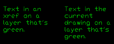
One of the things I notice when setting up AutoCAD 2010 or Civil 3D 2010 on a new computer is that drawings containing xreferenced drawings don't look the same as they did when I opened them in previous versions of AutoCAD. Now I'm not talking about having different colors for layers. You can check the layers and you'll still see red, yellow, green, etc. However, an object in the current drawing on a layer that's green looks different from an object in an xreferenced drawing that is also on a layer that's green. Here's an example of what you see with a black model space background:

It does make it very clear what is in the xreferenced drawing and what is in the current drawing, but it can be a bit difficult to see the objects in the xreferenced drawing with a black background such as this. Here are two ways to change this setting.
The first method is to type XDWGFADECTL at the command prompt and set it to 0 (zero) if you want xref objects to appear without fading as seen in previous versions of AutoCAD or Civil 3D.
The second method is through the System Variable Editor:
In the default Civil 3D workspace of Civil 3D 2010, select the "Express Tools" ribbon tab.
 Now left click on the System Variable Editor icon.
 Once the System Variable Editor dialog box opens, scroll down the list of variables and left click on XDWGFADECTL. The Initial Value is 70 and the Current Value will probably be 70 as well.
Left click in the white box labeled New Value.
Change the value to 0 (zero), but DON'T PRESS ENTER.
Left click on another system variable in the list such as XFADECTL, then left click back on XDWGFADECTL. The New Value should still be set to 0 (zero).
Now left click on the OK command button.
Here's the same text after changing this system variable:
 NOTE: This system variable has settings other than a simple "on" and "off" setting. Here's a description and valid values for the XDWGFADECTL system variable:
The XDWGFADECTL system variable controls the dimming for all DWG xref objects. The valid XDWGFADECTL system variable value is between -90 and 90.
When the value is 0 (zero), DWG xref objects are not faded.
When the value is positive, controls the percent of fading up to 90 percent.
When the value is negative, xref objects are not faded, but the value is saved for switching to that value by changing the sign.
One of the things I notice when setting up AutoCAD 2010 or Civil 3D 2010 on a new computer is that drawings containing xreferenced drawings don't look the same as they did when I opened them in previous versions of AutoCAD. Now I'm not talking about having different colors for layers. You can check the layers and you'll still see red, yellow, green, etc. However, an object in the current drawing on a layer that's green looks different from an object in an xreferenced drawing that is also on a layer that's green. Here's an example of what you see with a black model space background:

It does make it very clear what is in the xreferenced drawing and what is in the current drawing, but it can be a bit difficult to see the objects in the xreferenced drawing with a black background such as this. Here are two ways to change this setting.
The first method is to type XDWGFADECTL at the command prompt and set it to 0 (zero) if you want xref objects to appear without fading as seen in previous versions of AutoCAD or Civil 3D.
The second method is through the System Variable Editor:
In the default Civil 3D workspace of Civil 3D 2010, select the "Express Tools" ribbon tab.
 Now left click on the System Variable Editor icon.
 Once the System Variable Editor dialog box opens, scroll down the list of variables and left click on XDWGFADECTL. The Initial Value is 70 and the Current Value will probably be 70 as well.
Left click in the white box labeled New Value.
Change the value to 0 (zero), but DON'T PRESS ENTER.
Left click on another system variable in the list such as XFADECTL, then left click back on XDWGFADECTL. The New Value should still be set to 0 (zero).
Now left click on the OK command button.
Here's the same text after changing this system variable:
 NOTE: This system variable has settings other than a simple "on" and "off" setting. Here's a description and valid values for the XDWGFADECTL system variable:
The XDWGFADECTL system variable controls the dimming for all DWG xref objects. The valid XDWGFADECTL system variable value is between -90 and 90.
When the value is 0 (zero), DWG xref objects are not faded.
When the value is positive, controls the percent of fading up to 90 percent.
When the value is negative, xref objects are not faded, but the value is saved for switching to that value by changing the sign.
Subscribe to:
Posts (Atom)